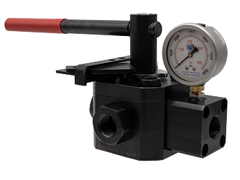
Hydraulic Lockout Valve Manual L-O-X® Valve

- Actuation - Manual handle bar with 90° rotation, to control ON/OFF positions
- Quick Energy Dump - Full size Tank ports provide rapid bleed of downstream hydraulic energy (T1) and rapid bypass of pump flow (T2).
- Locking Position - Design only allows the valve to be lockable in the OFF (bypassing & bleeding) position
- Nitrile Seals - Buna-N seals for easy shifting, even after long periods of inactivity
- Visible Pressure Indication Option - Includes integrated sensing port on port A for pressure verification with either a gauge (optional), electrical pressure switch (optional) or a transducer (optional)
- Mounting - Inline or surface
- 4-Way Design - Includes two Tank ports that, in the OFF position, are used to dump energy from downstream (T1) and bypass pump flow to the reservoir (T2). If bypassing is not necessary, only use T1.
- 🔗 Click here to view product video (Under Safety Products)
loading...
loading...
Product Overview
The ROSS Controls Hydraulic Manual L-O-X Valve is a 4-way manual isolation valve designed to provide safe, OSHA-compliant lockout/tagout (LOTO) energy isolation for hydraulic machine circuits. The valve blocks downstream hydraulic energy and simultaneously provides two tank port functions: T1 rapidly bleeds residual downstream hydraulic energy back to the reservoir, and T2 bypasses pump flow directly to the reservoir when the valve is in the OFF (lockout) position, protecting the hydraulic pump from deadheading during extended lockout periods.
The 4-way valve design is a defining feature of the Hydraulic L-O-X that distinguishes it from a simple shutoff valve. When switched to the OFF position, both downstream circuit pressure (via T1) and pump bypass pressure (via T2) are managed simultaneously. If only blocking downstream energy is required (and pump bypass is not needed for the application), only T1 is used. The two tank port design ensures maximum flexibility for integration into hydraulic power unit circuits of varying complexity.
The valve design allows it to be locked only in the OFF (bypassing and bleeding) position. It is not possible to lock the valve in the ON position, which is a fundamental requirement of OSHA 1910.147 and ANSI Z244.1 lockout/tagout standards. This design constraint ensures that operators cannot inadvertently lock a valve in the energized state. A 90-degree rotation of the manual handle bar actuates the valve between ON and OFF positions.
The Hydraulic L-O-X is available in three port sizes (1/2 inch, 3/4 inch, and 1-1/4 inch) with corresponding flow rates of 20, 35, and 50 gpm and is pressure-rated to 6000 psi (414 bar), exceeding the maximum pressure of most industrial hydraulic systems. Buna-N seals provide easy shifting even after extended periods of inactivity, which is critical for a lockout valve that may sit in the ON position for weeks between maintenance events. A visible pressure indication option with integrated sensing port allows connection of a pressure gauge, electrical pressure switch, or transducer to verify that downstream pressure has been fully dissipated before personnel access.
Key Engineering Features
- 4-Way Design with Dual Tank Ports - Two tank ports in the OFF position: T1 dumps residual downstream hydraulic energy rapidly to the reservoir, and T2 bypasses active pump flow directly to reservoir. This protects the hydraulic pump from pressure relief valve cycling or pump damage during extended lockout periods when the pump continues to run.
- Lockable Only in OFF Position - The mechanical design of the valve only permits the padlock to be inserted and locked when the valve is in the OFF (bypassing and bleeding) position. It is mechanically impossible to lock the valve in the energized (ON) state, satisfying the fundamental OSHA and ANSI lockout/tagout design requirement.
- 90-Degree Manual Handle Bar Rotation - Clear, positive two-position actuation with a 90-degree handle rotation between ON and OFF states provides unambiguous visual position indication and requires deliberate, conscious actuation. The handle position is immediately visible from a distance, confirming valve state without requiring close inspection.
- Rapid Energy Dump via Full-Size Tank Ports - Full-size T1 tank port provides rapid bleed of downstream hydraulic energy, minimizing the time required for downstream pressure to reach zero and reducing the total time to achieve a safe, verified lockout state. Faster energy dissipation improves productivity during routine lockout/tagout events.
- Visible Pressure Indication Option - Integrated sensing port on Port A allows installation of an optional pressure gauge, electrical pressure switch, or transducer for direct verification that downstream hydraulic pressure has dropped to zero before personnel enter the hazardous area. This addresses the OSHA requirement to verify energy dissipation after lockout.
- Buna-N Seals for Long-Term Reliability - Buna-N (nitrile) seals throughout the valve provide easy, low-friction shifting even after extended periods of inactivity. Lockout valves frequently remain in the ON position for weeks or months between lockout events; Buna-N seals maintain their mechanical properties and sealing surfaces during these idle periods, ensuring the valve shifts positively when needed.
- High-Pressure Rating to 6000 psi - Rated to 6000 psi (414 bar), exceeding the maximum operating pressure of most standard industrial hydraulic systems (typically 3000-5000 psi). This margin provides confidence in the valve's structural integrity and seal performance across the full range of typical industrial hydraulic pressures.
- Inline and Surface Mounting - Supports both inline mounting in the hydraulic supply line and surface mounting to panels or machine frames, providing installation flexibility for retrofit and new machine applications with different hydraulic line routing configurations.
- Three Port Sizes - Available in 1/2 inch (20 gpm), 3/4 inch (35 gpm), and 1-1/4 inch (50 gpm) port sizes with corresponding flow ratings, covering the majority of industrial hydraulic circuit sizes from small machine tools to large presses and transfer lines.
- Carbon Steel and Buna-N Construction - Carbon steel body construction and Buna-N seals provide the mechanical strength required for 6000 psi service and broad compatibility with mineral oil hydraulic fluids used in standard industrial hydraulic systems.
Technical Specifications
General Specifications
| Parameter | Specification |
| Valve Type | 4-Way Manual Isolation (Lockout/Tagout) |
| Function | Blocks downstream supply; bleeds downstream circuit (T1); bypasses pump flow to reservoir (T2) |
| Actuation | Manual handle bar with 90-degree rotation |
| Lockable Position | OFF position only (bypassing and bleeding) |
| Mounting | Inline or surface |
| Maximum Pressure Rating | 6000 psi (414 bar) |
| Seal Material | Buna-N (Nitrile) |
| Body Material | Carbon Steel |
| Seal Materials (additional) | Delrin and Buna-N (Nitrile Rubber) |
| Pressure Verification | Integrated sensing port on Port A; accepts gauge, pressure switch, or transducer (optional) |
| Flow Media | Hydraulic mineral oil (standard industrial hydraulic fluids) |
Flow Performance Data
Port sizes, flow ratings, and nominal flow capacity for the Hydraulic L-O-X valve. All sizes rated to 6000 psi.
| Port Size | Flow Rate | Max Pressure | Body Material | Seal Material |
| 1/2 inch | 20 gpm | 6000 psi (414 bar) | Carbon Steel | Buna-N + Delrin |
| 3/4 inch | 35 gpm | 6000 psi (414 bar) | Carbon Steel | Buna-N + Delrin |
| 1-1/4 inch | 50 gpm | 6000 psi (414 bar) | Carbon Steel | Buna-N + Delrin |
Certifications & Compliance
| Certification/Standard | Detail |
| OSHA 1910.147 | Designed to meet OSHA 1910.147 Subpart J Control of Hazardous Energy (Lockout/Tagout) requirements. The valve is lockable only in the OFF (de-energized) position, satisfying the OSHA requirement for lockout devices. |
| ANSI Z244.1 | Designed to conform with ANSI Z244.1 Control of Hazardous Energy - Lockout, Tagout and Alternative Methods. The valve provides the required manual energy isolation device with positive lockout in the de-energized position. |
| ISO 14118 | Designed to comply with ISO 14118 Safety of Machinery - Prevention of Unexpected Start-up, which requires energy isolation devices to be lockable in the de-energized position. |
| CSA Z460 | Designed to conform with CSA Z460 Control of Hazardous Energy - Lockout and Other Methods for Canadian installations. |
| Safety Category | Manual lockout valve provides Category 1 energy isolation function. Integration into higher safety category systems is achieved by combining with monitoring and control components. |
| Design Compliance | 4-way design with dual tank ports, lockable only in OFF position, and integrated pressure sensing port provides all features required by OSHA, ANSI, ISO, and CSA lockout/tagout standards for hydraulic energy isolation devices. |
Typical Applications & Industries
Hydraulic Press and Stamping Lines
- Hydraulic press main supply line energy isolation before tooling change, die adjustment, or press bed access. The L-O-X valve isolates the press circuit and rapidly vents downstream accumulator and cylinder pressure through T1 while T2 continues to circulate pump flow to the reservoir during the lockout period.
- Stamping line feed system hydraulic circuits where the L-O-X valve provides single-point isolation of the feed cylinder and clamp circuits before operators access the die area for jam clearing or part retrieval.
- Hydraulic press overload protection circuit isolation before maintenance on the overload relief valve, pressure transducer, or pressure switch components.
Injection Molding Machines
- Injection molding machine main hydraulic supply line isolation before mold change, purging operations, or hydraulic cylinder maintenance. The L-O-X valve safely isolates and vents the entire machine hydraulic circuit.
- Hydraulic clamping circuit isolation for mold change procedures, where the L-O-X valve provides a convenient lockout point close to the clamp unit for maintenance personnel.
- Injection unit hydraulic circuit isolation for barrel removal, screw pull, or check ring replacement requiring safe access to the hydraulic actuators.
Metal Forming and Fabrication
- Hydraulic shear and guillotine hydraulic supply isolation before blade removal or blade gap adjustment. The L-O-X valve prevents unexpected blade movement and provides the required lockout point for OSHA compliance.
- Hydraulic tube bender and pipe bender circuit isolation before tooling change or mandrel replacement requiring access to hydraulic actuators and clamps.
- Hydraulic roll forming machine supply line isolation before roll adjustment or stand maintenance, where multiple actuators are supplied from a common hydraulic circuit.
Steel Service Centers and Metal Processing
- Hydraulic coil car and reel hydraulic supply line isolation before coil change or maintenance on mandrel and hold-down actuators.
- Cut-to-length line hydraulic feed and clamp circuit isolation before blade change or straightener maintenance.
- Hydraulic slitter line knife carriage and hold-down circuit isolation before knife change or arbor maintenance operations.
General Industrial Hydraulic Systems
- Hydraulic power unit zone isolation valve for sectioning large hydraulic systems into independently isolable zones. The L-O-X valve provides the lockout point for each zone, enabling zone-level LOTO without shutting down the entire hydraulic power unit.
- Hydraulic cylinder circuit isolation for cylinder replacement or seal replacement maintenance without requiring a full hydraulic system shutdown.
- Hydraulic actuated gate and valve operator circuits on chemical processing equipment, where the L-O-X valve provides the isolation point before maintenance on actuators in hazardous process environments.
Mining and Heavy Equipment
- Hydraulic boom and arm circuit isolation on material handling equipment before attachment change or cylinder service.
- Hydraulic clamp and conveyor drive circuit isolation on mining equipment before maintenance on hydraulic actuators in remote or underground installations.
- Hydraulic steering and braking circuit isolation points on mobile industrial equipment for service and maintenance procedures.
Ordering and Model Number Configuration
The Hydraulic L-O-X valve is ordered by port size. Contact ROSS Controls for complete model numbers and configuration options including surface mount versus inline mount and pressure sensing port options.
|
Hydraulic L-O-X Valve - Order by Port Size and Configuration:
Port Size Flow Rate Pressure Rating Mounting - - - - - - - - - - - - - 1/2 inch 20 gpm 6000 psi Inline or Surface 3/4 inch 35 gpm 6000 psi Inline or Surface 1-1/4 inch 50 gpm 6000 psi Inline or Surface
Options: Pressure gauge (optional, via sensing port on Port A) Electrical pressure switch (optional, via sensing port on Port A) Transducer (optional, via sensing port on Port A)
Contact ROSS Controls at (800) 438-7677 for complete model numbers and configuration options. |
The Hydraulic L-O-X valve is a manual lockout valve and has no solenoid or electrical actuation. It is not suitable as an automatic safety shutoff valve.
The valve is designed for use with standard mineral oil hydraulic fluids. Verify fluid compatibility for synthetic, fire-resistant, or water-glycol fluids before specifying.
For applications requiring only downstream energy bleed without pump bypass, connect only the T1 port to the reservoir return line. The T2 port is used when bypassing active pump flow during the lockout period.
Contact ROSS Controls for complete model numbers, CAD files, installation instructions, and application support at (800) 438-7677 or rosscontrols.com.
Accessories
Pressure Verification Accessories
The integrated sensing port on Port A accepts optional pressure verification accessories. A pressure gauge provides local visual indication. An electrical pressure switch can be wired to the machine control system or safety relay for electrical verification of zero pressure. A pressure transducer provides continuous pressure monitoring and data logging capability.
Padlocks and Lockout Tagout Hardware
Standard industrial padlocks are compatible with the lockout hole in the Hydraulic L-O-X valve handle. For group lockout procedures, hasp devices with multiple lock attachment points allow each maintenance technician to apply their personal padlock before entry. Lockout tags provide written documentation of the lockout date, reason, and responsible person.
Related Products & Accessories
- HBB Series Hydraulic Block & Bleed Valves - Electrically operated redundant hydraulic block and bleed valve systems for automated safety stop applications requiring external safety monitoring. https://www.rosscontrols.com/en/series/1311-hbb
- HBH Series Hydraulic Block & Stop Valves - Electrically operated redundant hydraulic block and stop valve systems with load holding capability for safe stopping of hydraulically controlled cylinders. https://www.rosscontrols.com/en/series/1312-hbh
- HDBH Series Hydraulic Dual Block & Stop Valves - D03 sandwich-mount redundant dual blocking valve for safe stopping of hydraulic actuators at directional valve manifold stations. https://www.rosscontrols.com/en/series/1313-hdbh
- 15 Series Pneumatic Lockout L-O-X Valves - Manual lockout valves for pneumatic energy isolation, the pneumatic counterpart to the hydraulic L-O-X. Available in port sizes 1/4 inch through 2 inch. https://www.rosscontrols.com/en/series/1287-lockout-valves-15-series
- ElectroGuard Energy Isolation System - Complete integrated electrical, pneumatic, and hydraulic energy isolation system with remote lockout stations for complex machine lockout/tagout procedures. https://www.rosscontrols.com/en/series/1314-electroguard
- e L-O-X Electrical Isolation Devices - Local electrical energy isolation and verification devices for OSHA-compliant lockout/tagout of electrical energy sources at machine level. https://www.rosscontrols.com/en/series/1315-electrical-isolation-devices
Frequently Asked Questions (FAQ)
Q: What is the purpose of the two tank ports (T1 and T2) on the Hydraulic L-O-X valve?
A: T1 provides rapid bleed of downstream hydraulic energy (stored in cylinders, accumulators, and circuit hoses) back to the reservoir when the valve is switched to OFF. T2 provides bypass of active pump flow directly to the reservoir when the valve is in the OFF position. Without T2, the running hydraulic pump would be deadheaded against the closed valve, causing the system relief valve to continuously bypass flow and generating heat and noise. If the hydraulic pump will be stopped before lockout, only T1 is needed.
Q: Why can the valve only be locked in the OFF position?
A: OSHA 1910.147, ANSI Z244.1, ISO 14118, and CSA Z460 all require that lockout devices be capable of locking only in the de-energized (OFF) state. The Hydraulic L-O-X mechanical design physically prevents insertion of a padlock except when the valve handle is in the OFF position. This eliminates the risk of accidentally locking the valve in the energized position and ensures compliance with these standards.
Q: How do I verify that downstream pressure has reached zero?
A: The integrated sensing port on Port A accepts an optional pressure gauge, electrical pressure switch, or pressure transducer. Before personnel entry, visually check the pressure gauge reading or use the electrical pressure switch signal in the machine safety circuit to confirm that downstream pressure is zero. This verification step is required by OSHA before declaring the lockout/tagout complete and entering the hazardous area.
Q: What is the maximum pressure rating?
A: The Hydraulic L-O-X valve is rated to 6000 psi (414 bar), exceeding the typical maximum operating pressure of most industrial hydraulic systems (3000 to 5000 psi). This provides a pressure margin for system pressure spikes and simplifies specification across a range of hydraulic system pressures.
Q: What port sizes are available and what are the corresponding flow rates?
A: Three port sizes are available: 1/2 inch (20 gpm), 3/4 inch (35 gpm), and 1-1/4 inch (50 gpm). Select the port size that matches the hydraulic supply line size and flow requirement of the circuit being isolated.
Q: Does the Hydraulic L-O-X valve provide any continuous position monitoring?
A: No. The Hydraulic L-O-X is a manual valve without position switches or electrical feedback. For applications requiring automated position monitoring or integration with a safety control system, use the electrically operated HBB or HBH Series hydraulic safety valves, which include PNP inductive position switches.
Q: Is the Hydraulic L-O-X suitable as an automated safety shutoff valve?
A: No. The Hydraulic L-O-X is a manual valve designed for human-operated lockout/tagout procedures. It has no electrical actuation and is not suitable for automated or solenoid-controlled safety shutoff functions. For automated safe shutoff with external monitoring, use the HBB or HBH Series.
Q: What materials are the valve body and seals made from?
A: The valve body is carbon steel. Seals include Buna-N (nitrile rubber) and Delrin components. This construction provides compatibility with standard mineral oil hydraulic fluids and the mechanical strength required for 6000 psi service.
Q: Why are Buna-N seals important for a lockout valve?
A: Buna-N seals maintain their physical properties and sealing surfaces during extended periods of static contact under pressure (when the valve is ON during production), and they shift easily even after long idle periods in either position. A lockout valve that is stiff or requires excessive force to operate may be bypassed by operators who find it inconvenient, undermining the safety program. Buna-N seals ensure the valve shifts positively and easily every time.
Q: Can I use the Hydraulic L-O-X without connecting T2?
A: Yes. If the hydraulic power unit will be shut off before lockout, or if pump bypass is not required for the application, T2 can be left unconnected (capped) and only T1 is used for downstream bleed. This simplifies installation in applications where pump bypass is not needed.
Q: Is there a mounting orientation requirement?
A: The Hydraulic L-O-X supports both inline and surface mounting with no mandatory orientation requirement. Select the mounting orientation that provides convenient access for the operator performing lockout/tagout, ensures the valve handle position is clearly visible, and allows easy access to the padlock hole.
Q: Does the Hydraulic L-O-X meet OSHA lockout/tagout requirements?
A: Yes. The valve is designed to meet OSHA 1910.147, ANSI Z244.1, ISO 14118, and CSA Z460 requirements for hydraulic energy isolation devices. The key design features required by these standards are: lockable only in OFF position, ability to accept a standard padlock, and provision for verifying energy dissipation (via the sensing port). Integration into a complete LOTO program requires additional procedural and administrative controls as defined in each standard.
Installation & Maintenance Guidelines
- Install the Hydraulic L-O-X valve in the main hydraulic supply line serving the equipment or zone being isolated, upstream of all hydraulic actuators in the circuit.
- Connect Port T1 to the hydraulic reservoir return line. If pump bypass during lockout is required, also connect Port T2 to the reservoir return line.
- Mount in a location that is accessible to all maintenance personnel who will perform lockout/tagout, with the handle and padlock hole clearly visible and reachable without climbing or special access equipment.
- Connect the optional pressure gauge or pressure switch to the sensing port on Port A before commissioning. Verify that the pressure drops to zero on the indicator when the valve is switched to OFF.
- Verify valve function during commissioning: switch to OFF, apply padlock, confirm downstream pressure drops to zero on Port A sensing port, and verify pump flow is being diverted to reservoir via T2 (if connected).
- Label the valve with its lockout isolation point designation per the facility lockout/tagout procedure. Use ANSI Z535-compliant safety labels identifying the energy source and isolation procedure.
- Verify that the T1 return line is adequately sized for the downstream circuit volume. An undersized return line will slow the rate of downstream pressure bleed and increase the time to verified lockout.
- Do not install check valves downstream of the Hydraulic L-O-X valve T1 bleed port that would prevent downstream circuit pressure from draining to the reservoir.
- Inspect the valve handle and lockout hole annually for wear, corrosion, or damage. A lockout valve that cannot be easily shifted or locked is a safety hazard and must be replaced.
- Include the Hydraulic L-O-X valve in the facility's energy control procedure documentation, identifying it by location, energy type (hydraulic), and the specific machines or circuits it isolates.
Warranty & Global Support
ROSS Controls provides a one-year warranty on all products, covering defects in material and workmanship from the date of purchase.
Global technical support is available through ROSS Controls offices in the USA (headquarters in Ferndale, Michigan), Canada, Brazil, Germany, France, United Kingdom, India, China, and Japan.
Contact ROSS Controls USA at +1-248-764-1800 or (800) 438-7677, or visit rosscontrols.com for product configuration, application engineering support, installation instructions, and distributor locator services.
For hydraulic system safety consulting, LOTO procedure development support, or on-site application review, contact ROSS Controls at (800) 438-7677.
Download Catalog: https://www.rosscontrols.com/en/series/3133-hydraulic-lockout-valve
Download Documents
Hydraulic Lockout Valve