Hydraulic Energy Isolation
OSHA 1910.147 The Control of Hazardous Energy (Lockout/Tagout) requires all energy sources to be isolated, verification of the removal of residual hazardous energy, and the locking out of the isolating devices. It also requires procedures and training be in place for these processes and specifically mentions electrical, pneumatic, and hydraulic energies.
ANSI/ASSP Z244.1 was used as the basis for the OSHA standard over 40 years ago but has consistently been updated with the most recent revision taking place in 2024. It has some specific requirements such as:
- have the lockout devices accessible and conveniently located outside of the hazardous area and at a convenient heigh
- the energy isolating devices should have the capability to be locked in the energy isolating position by accepting a hasp or has a locking mechanism built into it.
Furthermore, ANSI B11.0 and PMMI B155.1 add additional requirements for machinery for hydraulic and pneumatic systems. Safety shutoffs and exhaust devices shall:
- be capable of being locked in the off position only
- have a properly sized exhaust port
- have a pressure indicator.
While “exhaust” is used exclusively used for pneumatic systems, the same principles should be applied to a hydraulic shutoff and bleed to tank valve.
- Only being locked in the off position prevents an inexperienced or distracted employee from accidentally locking it in the energized position.
- Having a properly sized path to remove energy allows its removal in a prompt manner. Due to its incompressibility, hydraulic system pressure can be removed by the removal of a small amount of hydraulic fluid. However, a system that is under load or has an accumulator will require additional time to remove the volume of oil and pressure. A full ported valve bleeding to tank allows this to happen much more rapidly than through a smaller passage.
- A pressure indicator is required to verify the release of hazardous energy.
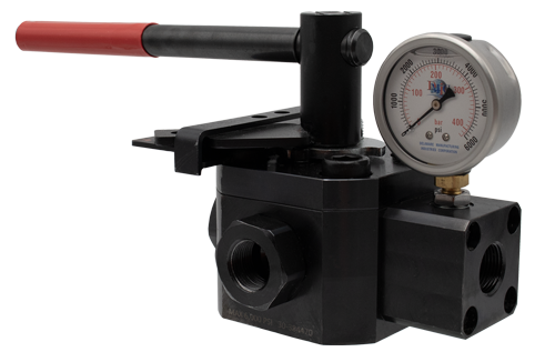
The new ROSS H L-O-X® Series is a hydraulic lockout valve designed to meet all global requirements and best practices for energy isolation and lockout of hydraulic energy. With a single handle it blocks supply and directs both downstream and supply pressure to tank to ensure there is no potential energy or pump damage if it has not been already shut off. The handle can only be locked in the energy isolated position. Most systems utilize two valves in a hydraulic lockout system; one to block and one to bleed. Both valves need to be isolated and locked in the correct position for the system to truly be isolated and prevent potential pressure buildup.
Hydraulic System Lockout Issues
In many cases it is believed that if the pump is locked out the system cannot add pressure to the system and therefore the machine is in a safe condition. In a simple machine circuit this may be completely accurate and acceptable. The supply is stopped and all downstream pressure is bled to tank rendering the system fully de-energized.

In systems where there is trapped pressure downstream due to a check valve on the system or closed center valves there must also be a way to remove the trapped pressure and verify its removal. It is quite common to have a check valve in a system that utilizes an accumulator. Placing the H L-O-X® prior to the check does not remove downstream pressure. The placement of the isolation valve between the check and accumulator could allow all pressure to be removed from the system in a time efficient manner.

The lockout valve can frequently be paired with a safety rated dual block and bleed valve as an alternative measure. The HBB Block and Bleed valve would remove pressure downstream of an accumulator without de-energizing the accumulator during production related tasks and the lockout in place to isolate all energy when maintenance is required.

Conclusion
The ROSS Hydraulic L-O-X® provides a single handle isolating device that can only be locked in the correct isolated (block and bleed) position and includes a gauge for verification. It can greatly simplify the hydraulic lockout process and reduce the potential for errors.
The challenge in hydraulic functional safety is developing a system that performs reliably while meeting safety standards. This involves redundancy and monitoring to ensure the highest levels of reliability and safety. One must fully understand the stresses that applying safety protocols can induce on an existing hydraulic system. Analyzing the effects, both upstream and downstream of the added safety components is critical in ensuring a reliable and secure safety system.