Double Valves for Clutch/Brake Control DM2® Series D, Self Monitored
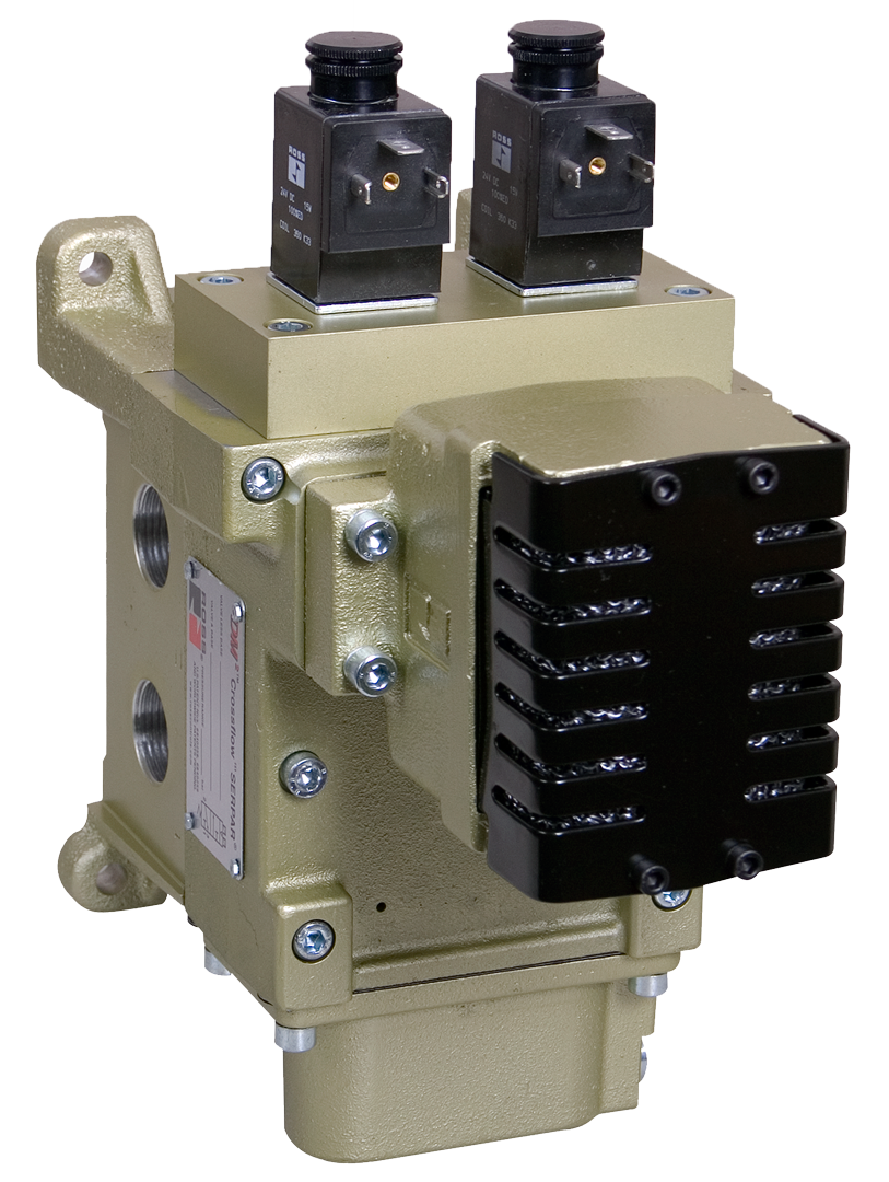
- Highly contaminant tolerant poppet construction
- High flow, clog resistant silencers
- Provides redundancy, dynamic monitoring and memory for the mechanical press industry regarding the control of pneumatically controlled clutch and brake applications
- Base mounted
Double Valves for Clutch/Brake Control DM2® Series D, Self Monitored Product Overview
The DM2® Series D double valve is a patented 3/2 normally closed valve (with an intermediate, lockout position) distinguished by SERPAR® Crossflow passages with poppet and spool valving on the main valve stems. This arrangement provides the valve’s outstanding flow characteristics and an integrated monitoring capability with total memory. The valve provides dynamic monitoring and dynamic memory.
Dynamic Monitoring means that all monitoring components change state on every valve cycle. Should the valve elements cycle asynchronously, the valve will exhaust downstream air and lock-out, prohibiting further operation.
Dynamic Memory within a monitoring system indicates that when a valve lock-out occurs, the valve will retain the fault information regardless of air or electrical changes. The DM2® system can only be reset by a defined operation/procedure, and will not self-reset (turning the valve off and on) or reset when inlet air supply is removed and re-applied. Such automatic resetting would conceal potential hazards from the operator.
Please refer to the side and below for links to easily navigate and download Double Valves for Clutch/Brake Control catalogs, installation instructions, and technical data. Additionally, you have the option to filter through all available options to discover the ideal Double Valves for Clutch/Brake Control variant that meets your requirements.
loading...
loading...
Product Overview
The ROSS Controls DM2 Series D is a patented family of self-monitored double valves purpose-built for the control of pneumatically actuated clutch and brake mechanisms on mechanical power presses and other critical safety applications. The DM2 Series D is a 3/2 normally closed valve with an intermediate lockout position, distinguished by SERPAR Crossflow passages with poppet and spool valving on the main valve stems. This patented arrangement delivers outstanding flow characteristics alongside an integrated monitoring capability with total memory.
The DM2 Series D provides both dynamic monitoring and dynamic memory in a single valve assembly. Dynamic Monitoring means that all monitoring components change state on every valve cycle. Should the valve elements cycle asynchronously, the valve immediately exhausts downstream air and locks out, prohibiting further machine operation. Dynamic Memory means that when a lockout occurs, the valve retains the fault information regardless of subsequent air or electrical changes. The system can only be reset by a defined procedure and will not self-reset when power or air supply is removed and reapplied. This permanent fault memory ensures that potential hazards cannot be concealed from the operator or safety system.
Available in five basic sizes (2, 4, 8, 12, and 30) with outlet port sizes from 1/4 inch to 2 inches, the DM2 Series D satisfies the latest industry standards requiring control-reliable, Category 3 and 4, or dynamically monitored valve capability. These valves are base mounted with NPT or G (BSPP) pipe threads, and inlet and outlet ports are provided on both sides of the base for flexible piping arrangements. Certifications include CE marking, DGUV, CSA/UL, and TSSA.
For design engineers specifying clutch/brake control valves, the DM2 Series D combines self-contained monitoring with exceptional dirt tolerance, high flow capacity through proven SERPAR Crossflow technology, and a patented lockout mechanism that eliminates the possibility of inadvertent reset. This combination satisfies OSHA 29 CFR 1910.217 requirements for mechanical power presses and meets Category 4, Performance Level e per ISO 13849-1.
Key Engineering Features
- Total Dynamic Monitoring - All monitoring components change state on every valve cycle, providing continuous verification of valve element synchronicity on each actuation and deactuation. Asynchronous element movement immediately triggers lockout and downstream exhaust.
- Complete Dynamic Memory - Valve retains fault information in the locked-out position regardless of air supply removal or electrical changes. Reset requires an overt, defined action and cannot be accomplished by cycling power or air supply, preventing concealment of hazards from operators.
- Patented SERPAR Crossflow Construction - Internal crossflow passages with poppet and spool valve elements deliver outstanding flow characteristics and inherent fault detection. If one element fails to close, outlet pressure remains below 1% of inlet pressure due to the crossflow geometry.
- Dual Poppet Design with Dirt Tolerance - Highly contaminant-tolerant poppet construction with PTFE backup rings on pistons operates reliably with or without in-line lubrication, reducing maintenance intervals in contaminated environments.
- High-Flow, Clog-Resistant Silencers - All models include integrated high-flow, clog-resistant exhaust silencers, maintaining exhaust capacity and preventing back pressure buildup that could affect valve response timing.
- Base-Mounted Construction - Base-mounted with captive valve-to-base mounting screws. Inlet and outlet ports on both sides of the base provide flexible piping options. Plugs for unused ports are included with every assembly.
- Optional Status Indicator - Pressure switch status indicator provides both normally open and normally closed contacts, giving the press control system feedback on whether the valve is in the ready-to-run or lockout condition. Can be ordered installed or added separately to any DM2 base.
- Two-Stage Intermediate Pilot (Sizes 12 and 30) - For the two largest valve sizes, intermediate pilot boosters increase pilot air flow for fast valve response while keeping electrical power requirements equivalent to the smaller sizes, reducing solenoid current demands.
- Multiple Reset Options - Supports remote pneumatic reset, optional solenoid reset, and manual push-button reset, allowing system designers to choose the reset method that best fits their machine control architecture.
- Broad Certification Portfolio - CE marked for applicable directives, DGUV certified (HSM 06008), CSA/UL listed, and TSSA certified for appropriately tested valve configurations, satisfying requirements across multiple international jurisdictions.
Technical Specifications
General Specifications
| Parameter | Specification |
| Valve Function | 3/2 Normally Closed (with intermediate lockout position) |
| Construction Design | Dual Poppet with SERPAR Crossflow passages |
| Actuation | Solenoid Pilot Controlled (two solenoids, rated for continuous duty) |
| Monitoring | Internal Dynamic Monitoring with Complete Memory (self-monitored) |
| Mounting | Base mounted; preferably horizontal (valve on top) or vertical with pilot solenoids on top |
| Basic Sizes Available | 2, 4, 8, 12, 30 |
| Port Sizes (Inlet/Outlet) | 1/4", 3/8", 1/2", 3/4", 1", 1-1/2", 2" |
| Thread Options | NPT (N prefix) and G/BSPP (D prefix) |
| Flow Media | Filtered, lubricated or unlubricated compressed air (mineral oils per DIN 51519, viscosity classes 32-46) |
| Valve Body Material | Cast Aluminum |
| Poppet Material | Acetal and Stainless Steel |
| Seal Material | Buna-N |
| Minimum Operation Frequency | At least once per month to ensure proper function |
| Functional Safety Data | Category 4, PL e; B10D: 20,000,000; PFHD: 7.71x10⁻⁹; MTTFD: 301.9 years (nop: 662,400) |
| Safety Integrity Level | SIL 3 |
| Enclosure Rating | IP65 per DIN 40050 / IEC 60529 |
| Vibration/Impact Resistance | Tested to BS EN 60068-2-27 |
| Electrical Connection | EN 175301-803 Form A connector socket (M12 available with code 005) |
Temperature Ratings
Temperature ratings apply to all DM2 Series D valve sizes. Media temperature lower limit (40F/4C) requires moisture-free compressed air to prevent internal ice formation.
| Configuration | Ambient Temperature | Media Temperature |
| All Sizes - Ambient | 15 to 120F (-10 to 50C) | 40 to 175F (4 to 80C) |
Important: For media temperatures at or near 40F (4C), compressed air must be free of water vapor to prevent ice formation inside the valve that could affect response timing.
Electrical Data (Solenoid Pilot Valves)
Two solenoids per valve, both rated for continuous duty. Basic Sizes 2, 4, 12, and 30 share the same solenoid specifications; Basic Size 8 uses higher-power solenoids for the main pilot and a separate reset solenoid. Voltages at pressure switches must not exceed 250 volts.
| Voltage | Power Consumption |
| 24 VDC (Sizes 2, 4, 12, 30 - Primary and Reset) | 5.8 watts nominal (6.5 watts maximum) per solenoid |
| 120 VAC, 50/60 Hz (Sizes 2, 4, 12, 30 - Primary and Reset) | 5.8 watts nominal (6.5 watts maximum) per solenoid |
| 24 VDC (Size 8 - Primary solenoid) | 15 watts |
| 120 VAC, 50/60 Hz (Size 8 - Primary solenoid) | 36 VA inrush, 24.6 VA holding |
| 24 VDC (Size 8 - Reset solenoid) | 6.0 watts |
| 120 VAC, 50/60 Hz (Size 8 - Reset solenoid) | 15.8 VA inrush, 10.4 VA holding |
Flow Performance Data
Cv values and weights are for complete valve and base assemblies with status indicator and solenoid reset installed. Cv values listed are average for in-out (1-2) and out-exhaust (2-3) paths.
| Basic Size | Port Sizes (In/Out) | Cv (In-Out) | Cv (Out-Exhaust) | Weight lb (kg) |
| 2 | 1/4 or 3/8 in, 1/4 or 3/8 out | 2.17 | 3.66 | 5.0 (2.3) |
| 4 | 1/2 in, 1/2 or 3/4 out | 2.80 | 6.70 | 6.0 (2.8) |
| 8 | 3/4 in, 3/4 or 1 out | 4.63 | 12.55 | 9.1 (4.2) |
| 12 | 1 in, 1 or 1-1/2 out | 8.86 | 20.78 | 15.5 (7.1) |
| 30 | 1-1/2 in, 2 out | 20.22 | 53.68 | 32.6 (14.8) |
Response Time Formula: Valve Response Time (msec) = M + F x V, where M is the average time constant for parts movement, F is the fill/exhaust factor in msec per cubic inch of volume, and V is the downstream volume in cubic inches. Consult ROSS response charts for each basic size.
Certifications & Compliance
| Certification/Standard | Detail |
| Functional Safety - Category | Category 4, Performance Level e per ISO 13849-1:2015, the highest level for control-reliable pneumatic safety systems. |
| Safety Integrity Level | SIL 3 per IEC 62061:2001, suitable for integration into safety-instrumented systems for the most demanding press control architectures. |
| Reliability Data | B10D: 20,000,000 cycles; PFHD: 7.71x10⁻⁹; MTTFD: 301.9 years (based on nop: 662,400 operations per year). |
| DGUV (German Social Accident Insurance) | DGUV tested and certified (HSM 06008 - Sicherheit gepruft / tested safety), satisfying European occupational safety requirements for press control. |
| CE Marking | CE marked for applicable EU directives including Machinery Directive, confirming conformity with European health, safety, and environmental requirements. |
| CSA/UL | CSA/UL listed for appropriately tested valve configurations, satisfying North American electrical and safety standards. |
| TSSA | TSSA (Technical Standards and Safety Authority) certified for appropriately tested valves in Canadian jurisdictions. |
| Enclosure Protection | IP65 per DIN 40050 / IEC 60529, providing dust-tight and water jet protection for industrial environments. |
| OSHA Compliance | Designed to satisfy OSHA 29 CFR 1910.217 requirements for mechanical power presses employing pneumatically controlled clutch and brake mechanisms. |
Typical Applications & Industries
Mechanical Stamping Press Clutch/Brake Control
- Stamping press single-stroke and continuous-run clutch/brake control where OSHA 29 CFR 1910.217 mandates control-reliable double valve with dynamic monitoring and memory. DM2 Series D satisfies all monitoring and memory requirements of this regulation.
- Large-tonnage transfer press clutch/brake control requiring Category 4, PL e safety level with integral dynamic monitoring to detect partial valve failure before it can produce a hazardous press stroke.
- High-speed blanking and progressive die press lines where rapid response time and high exhaust Cv ratings (up to 53.68 for Size 30) are essential to achieve safe brake engagement within press control timing specifications.
- Servo-mechanical press retrofits where legacy double valves require upgrading to current Category 4 dynamic monitoring standards without replacing the press base piping layout.
Metal Forming and Forging Operations
- Forging press control where shock loads and vibration demand a valve with PTFE-backed piston rings and poppet construction to maintain sealing integrity over tens of millions of cycles.
- Coining and embossing press lines operating in oil-mist environments where the DM2 Series D tolerance for lubricated air and contamination-resistant poppet design ensures consistent operation without accelerated wear.
- Fine-blanking presses with high cycle rates, where the two-stage intermediate pilot system on Size 12 and 30 valves provides fast response times despite the large valve body volumes required for adequate flow capacity.
Energy Isolation and Lockout Systems
- Alternative lockout systems for energy isolation on press auxiliary circuits where the DM2 Series D permanent memory lockout ensures that once a fault is detected, the circuit cannot be restored without a positive manual reset procedure.
- Load-holding cylinder applications on press dies and tooling clamps where the 3/2 normally closed function ensures that air supply loss results in immediate cylinder exhaust rather than load retention.
- Safety zone entry control systems in press transfer lines where pneumatic safety gate and light curtain outputs require a Category 4 double valve with complete memory to prevent inadvertent restart.
- Hydraulic-pneumatic hybrid press controls where the pneumatic clutch/brake system must meet Category 4 isolation requirements while the hydraulic circuit provides slide motion control.
Automotive Body Shop and Metal Fabrication
- Automotive body stamping lines with robotic part transfer where press clutch/brake control must interface with a safety PLC while maintaining independent dynamic monitoring memory within the valve itself.
- Tube end-forming and roll-forming press equipment where lower tonnage presses benefit from the Size 2 or 4 DM2 Series D valves at 1/4 to 1/2 inch port sizes with full Category 4 monitoring.
- Metal building panel and roofing sheet press lines using progressive dies where the valve must survive continuous duty cycling at rates exceeding 60 strokes per minute across multiple daily shifts.
Ordering and Model Number Configuration
The DM2 Series D uses a structured model number system. Basic size, voltage, reset type, and options are encoded in the model number as shown below.
|
DM2 Series D Model Number Structure:
DM2 D N B 42 A 1 1 | | DM2 D Thread Basic Revision Voltage Reset Status Type Size Level Type Indicator
D = Series D
Thread Type: D = G (BSPP) | N = NPT Basic Size: 2 | 4 | 8 | 12 | 30 Voltage Code: A = 24 VDC B = 110-120 VAC, 50/60 Hz C = 220 VAC, 50/60 Hz (not available in US) D = 12 VDC Reset Type: 1 = Remote Pneumatic 2 = Solenoid 4 = Manual Status Ind.: 1 = With Status Indicator (pressure switch) X = Without Status Indicator
M12 Connection Option: Append '005' for M12 connector
Example: DM2DNB42A11 = G thread, Size 4, 120V AC, remote reset, with status indicator |
All standard DM2 Series D valves have NPT threads. To order G (BSPP) threads, use the D prefix before DM2 (e.g., DDM2DNB42A11).
Basic Size 2 uses Revision Level B; Basic Sizes 4, 8, 12, and 30 use Revision Level A.
Voltage Code C (220 VAC) is not available in the United States; OSHA regulations limit press control voltage to a maximum of 120 VAC.
The Status Indicator pressure switch has contacts rated at 5 amps at 250 VAC or 5 amps at 30 VDC. It can be ordered installed in the base or purchased separately (model 670B94) for field installation.
Connectors and wiring kits are ordered separately. Preassembled J-Box wiring kits (models 2283H77 through 2289H77) include cables for all three solenoids and the status indicator with M12 and DIN connectors.
Explosion-proof solenoid pilot valves are available for hazardous location press rooms; consult ROSS for configuration details.
Sub-Base Model Numbers by Port Size
| Basic Size | Inlet | Outlet | NPT Base | G Base | Status Indicator |
| 2 | 1/4" | 1/4" | 1872C91 | D1872C91 | No |
| 2 | 1/4" | 1/4" | 1873C91 | D1873C91 | Yes |
| 2 | 3/8" | 3/8" | 1874C91 | D1874C91 | No |
| 2 | 3/8" | 3/8" | 1875C91 | D1875C91 | Yes |
| 4 | 1/2" | 1/2" | 1697C91 | D1697C91 | No |
| 4 | 1/2" | 1/2" | 1698C91 | D1698C91 | Yes |
| 4 | 1/2" | 3/4" | 1699C91 | D1699C91 | No |
| 8 | 3/4" | 3/4" | 1701C91 | D1701C91 | No |
| 8 | 1" | 1" | 1703C91 | D1703C91 | No |
| 12 | 1" | 1" | 1705C91 | D1705C91 | No |
| 12 | 1" | 1-1/2" | 1707C91 | D1707C91 | No |
| 30 | 1-1/2" | 2" | 1709C91 | D1709C91 | No |
Accessories
Status Indicator (Pressure Switch)
Model 670B94. Actuates when the valve is in the ready-to-run condition; de-actuates during lockout or when inlet pressure is removed. Provides both normally open and normally closed contacts rated at 5A at 250 VAC or 5A at 30 VDC. Can be ordered installed or added to any existing DM2 base.
J-Box Wiring Kits
Junction box assemblies with 10-pin MINI connector for connection to the customer control system and four 5-pin M12 ports for the three solenoids and the status indicator. Kits include one 1-meter cable per port.
| Kit Number | Cable Length | Connector Type |
| 2283H77 | 5 m (16.4 ft) | EN 175301-803 Form A |
| 2284H77 | 10 m (32.8 ft) | EN 175301-803 Form A |
| 2288H77 | 5 m (16.4 ft) | M12 |
| 2289H77 | 10 m (32.8 ft) | M12 |
Reset Valves - Manual Pushbutton
3/2 normally closed manual pushbutton reset valves for remote air reset applications. Green and red button options.
| Type | Port Size | Color | NPT Model | G Model | Cv |
| Flush Pushbutton | 1/8" | Green | 1223B1FPG | D1223B1FPG | 0.6 |
| Flush Pushbutton | 1/8" | Red | 1223B1FPR | D1223B1FPR | 0.6 |
| Mushroom Button | 1/8" | Green | 1223B1MBG | D1223B1MBG | 0.6 |
Downstream Pressure Monitoring Switches
Factory-preset pressure switches for energy release verification, set to 5 psi (0.3 bar) falling. Available with EN 175301-803 Form A connector (model 586A86, 1/8 NPT) or M12 connector (model 1153A30, 1/8 NPT). Used to verify downstream pressure release to the next obstruction.
Electrical Connectors
Prewired connectors for EN 175301-803 Form A with 2-meter or 2.5-meter flying lead cables. Lighted connector versions available for 24 VDC and 120 VAC to provide visual solenoid-energized indication.
| Type | Length | Without Light | Lighted 24 VDC | Lighted 120 VAC |
| Prewired, 6-mm diameter | 2 m | 721K77 | 720K77-W | 720K77-Z |
| Prewired, 10-mm diameter | 2 m | 371K77 | 383K77-W | 383K77-Z |
| Conduit connector, 1/2" NPT | N/A | 723K77 | 724K77-W | 724K77-Z |
Related Products & Accessories
- SERPAR 35 Series with L-G Monitor (Series 183) - Internally monitored double valves with pneumatic L-G monitor for 1/2 to 2-inch port applications requiring internal lockout without external monitoring hardware. https://www.rosscontrols.com/en/series/183-double-valves-with-pneumatic-l-g-monitor-ports-1-2-to-2
- SERPAR 35 Series with L-G Monitor (Series 184) - Internally monitored double valves with pneumatic L-G monitor for 3/8 to 3/4-inch port sizes. https://www.rosscontrols.com/en/series/184-double-valves-with-pneumatic-l-g-monitor-ports-3-8-to-3-4
- SERPAR 35 Series with E-P Monitor (Series 186) - Internally monitored double valves with electro-pneumatic monitor, solenoid reset, available for single or dual input signal. https://www.rosscontrols.com/en/series/186-double-valves-with-electro-pneumatic-e-p-monitor
- CrossFlow 35 Series with Pressure Switches (Series 181) - Externally monitored double valves with pressure switches for 3/8 to 1-1/2-inch ports, requiring customer-supplied monitoring system. https://www.rosscontrols.com/en/series/181-double-valves-with-pressure-switches-ports-3-8-to-1-1-2
- Piping Flange Kits (Series 2839) - Connection piping kits with all required seals and mounting bolts for inline mounting of SERPAR and CrossFlow double valves. https://www.rosscontrols.com/en/series/2839-piping-flange-kits
- L-O-X Lockout Valves - Energy isolation lockout valves meeting OSHA 1910.147 for pneumatic system lockout/tagout during press maintenance. https://www.rosscontrols.com/en/series/1287-lockout-valves-15-series
Frequently Asked Questions (FAQ)
Q: What is the difference between dynamic monitoring and static monitoring in double valves?
A: Static monitoring checks valve state only at specific points in the cycle, typically at the start. Dynamic monitoring, as implemented in the DM2 Series D, verifies that both valve elements change state on every single actuation and deactuation. This means a valve element that is stuck open during operation is detected on the same cycle it fails, not on a subsequent test cycle.
Q: What does dynamic memory mean for press control safety?
A: Dynamic memory means the valve retains its locked-out condition even if air supply or electrical power is removed and reapplied. A valve with simple memory could be reset by cycling the air supply, which might conceal a fault from the operator. The DM2 Series D can only be reset by a deliberate manual, pneumatic, or solenoid reset action, ensuring that all lockout events are acknowledged and addressed.
Q: Does the DM2 Series D satisfy OSHA 29 CFR 1910.217?
A: Yes. OSHA 29 CFR 1910.217 for mechanical power presses requires that the pneumatic clutch/brake valve provide redundancy, dynamic monitoring, and memory. The DM2 Series D provides all three features in a single self-contained valve assembly, satisfying these requirements without requiring additional external monitoring hardware.
Q: What safety category and performance level does the DM2 Series D achieve?
A: The DM2 Series D achieves Category 4, Performance Level e per ISO 13849-1:2015 and SIL 3 per IEC 62061:2001. These are the highest levels available for pneumatic control components. The functional safety data is: B10D = 20,000,000 cycles; PFHD = 7.71x10⁻⁹; MTTFD = 301.9 years.
Q: How does the residual outlet pressure behave during a valve lockout?
A: When the DM2 Series D locks out due to asynchronous valve element movement, the crossflow passage geometry ensures that outlet pressure drops to less than 1% of inlet pressure. This immediate pressure exhaust prevents the press clutch from engaging during a fault condition.
Q: What port sizes are available and which basic size should I select?
A: Basic Size 2 covers 1/4 and 3/8-inch ports with Cv 2.17 in/out. Basic Size 4 covers 1/2 and 3/4-inch ports with Cv 2.80 in/out. Basic Size 8 covers 3/4 and 1-inch ports with Cv 4.63 in/out. Basic Size 12 covers 1 and 1-1/2-inch ports with Cv 8.86 in/out. Basic Size 30 covers 1-1/2 and 2-inch ports with Cv 20.22 in/out. Select based on the required Cv for the press clutch volume and acceptable fill/exhaust time.
Q: What reset methods are available?
A: Three reset types are available: Remote Pneumatic (code 1), which uses a 3/2 normally closed reset valve to apply inlet-equivalent air pressure to the reset port; Solenoid (code 2), which uses a solenoid-actuated reset valve rated for intermittent duty; and Manual (code 4), which uses an encapsulated push-button actuator directly on the valve. The solenoid reset option must not be continuously energized as this can cause burnout.
Q: Can DM2 Series D valves operate without in-line lubrication?
A: Yes. PTFE backup rings on the pistons enable the valve to operate with or without in-line lubrication. If lubrication is used, it must be petroleum-based with an aniline point between 180F and 220F and ISO 32 or lighter viscosity. Phosphate-type additives must be avoided.
Q: What is the operating pressure range, and does it differ by size?
A: Basic Size 2 operates at 45 to 150 psig (3.1 to 10.3 bar). Basic Sizes 4, 8, 12, and 30 operate at 30 to 120 psig (2.1 to 8.3 bar). Operating below the minimum pressure can result in incomplete valve element travel and unreliable monitoring response.
Q: How often must the DM2 Series D be cycled to ensure proper function?
A: The valve must be cycled at least once per month. This requirement ensures that all valve elements, pilot valves, and monitoring components exercise their full range of motion periodically, preventing stiction or contamination buildup that could cause asynchronous operation.
Q: What wiring is required for the solenoids and status indicator?
A: Standard valves use EN 175301-803 Form A DIN connectors at each solenoid. M12 connections are available by adding option code 005. ROSS J-Box wiring kit assemblies simplify wiring by providing a single 10-pin MINI connector to the customer control system, with four M12 ports for the three solenoids and the status indicator.
Q: Are 3D CAD models available for the DM2 Series D?
A: Yes. Downloadable CAD models are available for all DM2 Series D configurations through the ROSS Controls website at rosscontrols.com, enabling direct integration into machine design software without manual dimensioning.
Installation & Maintenance Guidelines
- Mount base horizontally with the valve body on top, or vertically with pilot solenoids pointing upward. These orientations ensure proper drainage and consistent pilot response timing.
- Install 5-micron filtration upstream of the DM2 Series D to prevent contaminants from interfering with poppet seating and crossflow passage operation.
- For remote pneumatic reset, connect the reset air supply using a 1/8-inch air line from a 3/2 normally closed reset valve. The reset pressure must equal the inlet pressure.
- Verify that inlet pressure is within the rated range before commissioning: 45 to 150 psig for Size 2, and 30 to 120 psig for Sizes 4 through 30.
- Do not restrict the exhaust port or install undersized silencers. Silencer flow capacity must equal or exceed the valve exhaust Cv rating to prevent back pressure.
- Remove the pipe plugs from the unused inlet and outlet ports only if both sides are to be connected. Install the provided plugs in any port not used to prevent contamination entry.
- After installation, perform a full actuation and deactuation cycle before connecting to the press clutch/brake to verify status indicator operation and confirm the valve exits the ready-to-run condition.
- For solenoid reset models, wire the reset solenoid for intermittent duty only. Continuous energization of the reset solenoid will cause burnout. Apply reset signal as a momentary pulse.
- Cycle the valve at minimum once per month as required for proper function verification per the manufacturer's specification.
- If the valve has been in lockout, identify and correct the root cause before resetting. Removing and reapplying air supply will not reset the valve. A deliberate reset action is required.
Warranty & Global Support
ROSS Controls provides a one-year warranty on all DM2 Series D products, covering defects in material and workmanship from date of purchase. The warranty is void if the product has been subjected to misuse, misapplication, improper maintenance, modification, or tampering.
Global technical support is available through ROSS offices in the USA (headquarters in Ferndale, Michigan), Canada, Brazil, Germany, France, United Kingdom, India, China, and Japan.
Contact ROSS Controls USA at +1-248-764-1800 or Technical Service at 1-888-TEK-ROSS (835-7677), or visit rosscontrols.com for product configuration, technical support, and distributor locator services.
For complete technical data, dimensional drawings, CAD models, and response time charts, visit the ROSS Controls DM2 Series D product page or contact ROSS Controls at (800) GET-ROSS (438-7677).
Download Catalog: https://www.rosscontrols.com/en/series/52-double-valves-for-clutch-brake-control
Download Documents
Double Valves for Clutch/Brake Control
