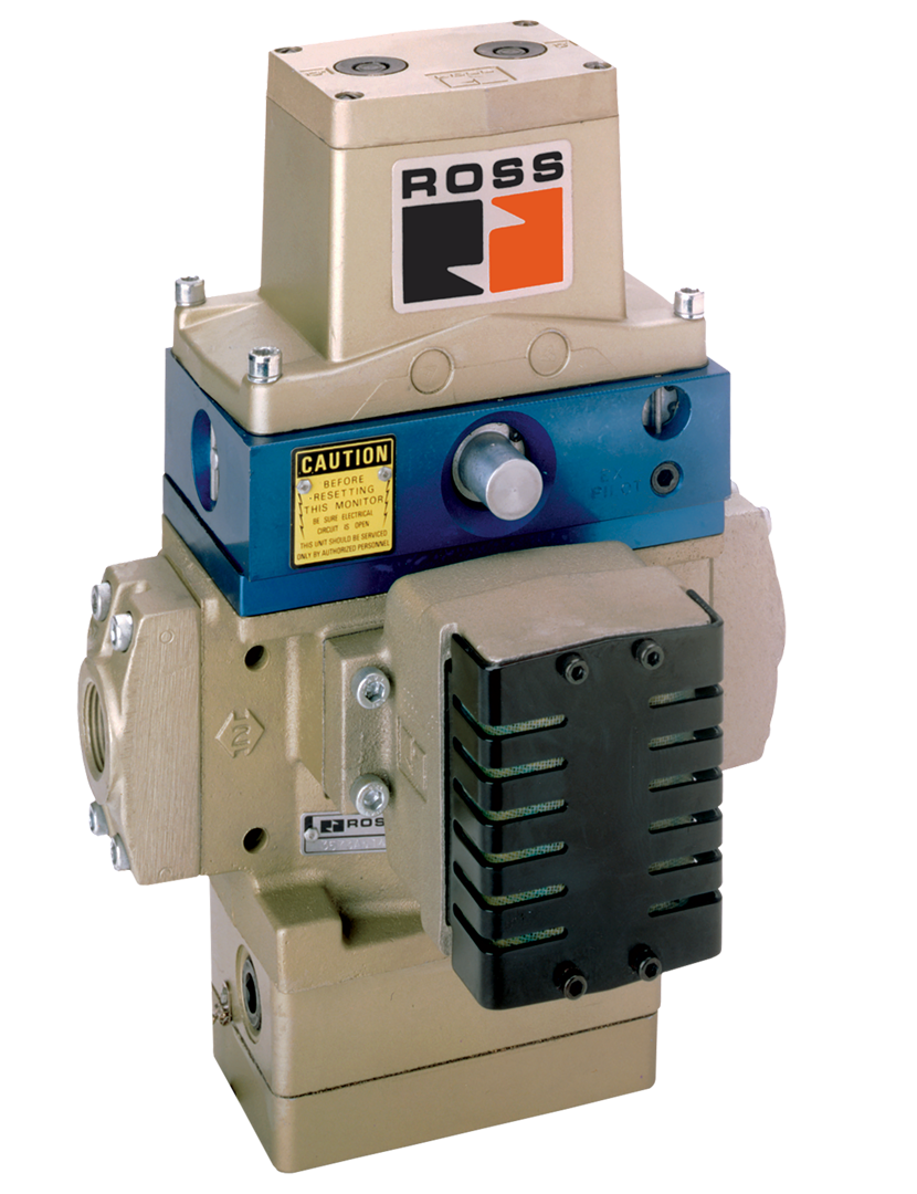
Double Valves with Pneumatic L-G Monitor, Ports 1/2 to 2 SERPAR® 35 Series
- Internal monitoring – requires no additional monitoring circuitry
- Automatic lock-out/inhibit upon detection of a malfunction
- Default to de-energized position upon fault detection
- Dedicated reset function
- No undesired automatic reset upon removal of electrical or pneumatic energy sources
- Built-in non-clogging silencers
Double Valves with Pneumatic L-G Monitor, Ports 1/2 to 2 SERPAR® 35 Series Product Overview
The SERPAR® Series valves are internally monitored double valves with a built-in monitoring device that checks for the proper operation of each valve element. If the internal monitor detects a valve fault on a particular cycle, the double valve will fail to a safe condition (all downstream air is exhausted) and the monitor will lock-out to inhibit further operation of the device. Normal operation can only be resumed by a momentary reset signal to the valve.
Please refer to the side and below for links to easily navigate and download Double Valves with Pneumatic L-G Monitor, Ports 1/2 to 2 SERPAR® 35 Series catalogs, installation instructions, and technical data. Additionally, you have the option to filter through all available options to discover the ideal Double Valves with Pneumatic L-G Monitor, Ports 1/2 to 2 SERPAR® 35 Series variant that meets your requirements.
loading...
loading...
Product Overview
The ROSS Controls SERPAR 35 Series Double Valves with Pneumatic L-G Monitor are internally monitored double valves for press clutch/brake control applications requiring port sizes from 1/2 inch through 2 inches. These valves are available in Basic Sizes 8, 12, and 30, covering flow coefficients (Cv) from 3.5 to 21 in the in-out direction and up to 43 in the exhaust direction, providing the high flow capacity needed for larger press clutch/brake volumes.
The SERPAR 35 Series with L-G monitor contains a built-in pneumatic lockout-gate (L-G) monitoring device that checks the proper synchronous operation of each valve element on every actuation and deactuation cycle. If the internal monitor detects a fault, the double valve exhausts all downstream air and locks out, inhibiting further operation until a deliberate reset signal is applied. The valve will not self-reset upon removal of electrical or pneumatic energy, ensuring the fault is acknowledged before operation can resume.
The L-G monitor operates pneumatically, requiring no external monitoring circuitry or electrical monitoring hardware. A lockout indicator port is provided so that a pressure switch, indicator light, or bell can be connected to alert operators when the valve has locked out. Manual reset models use internal valve pressure for reset; remote reset models require external pneumatic reset pressure equal to inlet pressure (minimum 60 psig for Sizes 8, 12, and 30).
SERPAR Crossflow technology is the foundation of these valves. Crossflow passages and spool valving on the main valve stems produce parallel, balanced flow paths that promote synchronous valve element movement and produce inherently high exhaust flow capacity. If one valve element fails open while the other closes, the crossflow geometry limits outlet pressure to less than 2% of inlet pressure while the monitoring spool detects the pressure imbalance and triggers lockout.
Key Engineering Features
- Internal Pneumatic L-G Monitoring - Requires no additional external monitoring circuitry. The built-in L-G spool and lockout pin detect asynchronous valve element movement on every cycle and execute lockout automatically without external logic devices.
- Automatic Lockout on Fault Detection - Upon detecting a valve element fault, the monitor immediately exhausts pilot air, allows both valve elements to close, and mechanically latches the L-G spool in the locked-out position to inhibit further valve actuation.
- No Undesired Automatic Reset - The L-G lockout pin holds the spool in the locked-out position regardless of air supply cycling or solenoid de-energization. Reset requires a deliberate pneumatic or manual action, preventing concealment of valve faults from safety personnel.
- Dedicated Reset Function - Manual reset models use internal pressure to release the lockout pin when a push-button is actuated. Remote reset models require a separate 3/2 normally closed reset valve connected to the reset port to provide momentary pneumatic reset pressure equal to inlet pressure.
- SERPAR Crossflow Poppet Construction - Parallel crossflow passages with dual poppet and spool valve elements deliver high flow Cv ratings and inherent fault containment. Outlet pressure remains below 2% of inlet during any single-element fault, protecting the press clutch from partial engagement.
- PTFE Backup Piston Rings - Enhance valve endurance and enable reliable operation with or without in-line lubrication, reducing FRL maintenance requirements in environments where continuous lubrication is impractical.
- Built-In High-Flow Non-Clogging Silencers - All SERPAR Size 8, 12, and 30 models include integrated exhaust silencers that resist clogging, maintaining exhaust Cv ratings and preventing backpressure from extending clutch/brake response times.
- Lockout Indicator Port - 1/8-inch lockout indicator port allows connection of a pressure switch, warning light, bell, or other device to provide operator notification when the valve is in the locked-out condition.
- Inlet Port Flexibility with Piping Flanges - Inline mounting with piping flanges allows connection from either side of the valve. The 2-inch port size option for Basic Size 30 requires a separate 1999H77 piping flange kit.
- CAD Models Available for Download - Downloadable CAD models available for all SERPAR Size 8, 12, and 30 configurations to simplify mechanical integration into press control enclosures and piping layouts.
Technical Specifications
General Specifications
| Parameter | Specification |
| Valve Function | 3/2 Normally Closed |
| Construction Design | Dual Poppet with SERPAR Crossflow passages |
| Actuation | Solenoid Pilot Controlled (two solenoids, rated for continuous duty) |
| Monitoring | Internal Pneumatic L-G (Lockout-Gate) Monitor |
| Mounting | Inline with piping flanges; preferably vertical with pilot solenoids on top |
| Basic Sizes Available | 8, 12, 30 |
| Port Sizes (In/Out) | 1/2", 3/4", 1", 1-1/4", 1-1/2", 2" (2" on Size 30 only, requires 1999H77 flange kit) |
| Thread Options | NPT (no prefix) and G/BSPP (D prefix) |
| Flow Media | Filtered air; 5-micron filtration recommended |
| Valve Body Material | Cast Aluminum |
| Poppet Material | Acetal (Delrin) and Stainless Steel |
| Seal Material | Buna-N |
| Minimum Operation Frequency | At least once per month to ensure proper monitoring function |
| Functional Safety Data | Category 4, PL e; B10D: 20,000,000; PFHD: 7.71x10⁻⁹; MTTFD: 301.9 years (nop: 662,400) |
| Safety Integrity Level | SIL 3 per IEC 62061:2001 |
| Enclosure Rating | IP65 per IEC 60529 / DIN 40050 |
| Electrical Connection | Terminal strip on Sizes 8, 12, 30 (cord-grip connectors ordered separately for Size 4) |
| Reset Type (Manual) | Uses internal valve pressure via push-button actuator on reset port |
| Reset Type (Remote Pneumatic) | Requires external 3/2 NC reset valve; reset pressure must equal inlet pressure; minimum 60 psig for Sizes 8, 12, 30 |
Temperature Ratings
Temperature limits apply to all SERPAR 35 Series L-G monitor valve sizes in this range. Media temperatures at the lower limit require dry, moisture-free compressed air.
| Configuration | Ambient Temperature | Media Temperature |
| All Sizes 8, 12, 30 - Ambient | 40 to 120F (4 to 50C) | 40 to 175F (4 to 80C) |
Important: At media temperatures near 40F (4C), compressed air must be free of water vapor to prevent ice formation inside valve passages, which can alter response time and monitoring accuracy.
Electrical Data (Solenoid Pilot Valves)
Solenoids are rated for continuous duty. The L-G monitor operates pneumatically and requires no separate electrical supply. Terminal strip on Sizes 8, 12, and 30. For Size 4 (in the 184 series), cord-grip connectors are used.
| Voltage | Power Consumption |
| 24 VDC (Sizes 8, 12, 30) | 14 watts per solenoid |
| 110-120 VAC, 50/60 Hz (Sizes 8, 12, 30) | 87 VA inrush, 30 VA holding per solenoid |
| 230 VAC, 50/60 Hz | 87 VA inrush, 30 VA holding per solenoid (not available in US) |
Flow Performance Data
Flow data for SERPAR 35 Series with L-G Monitor, Sizes 8, 12, and 30 (corresponding to 1/2 to 2-inch port sizes in this series). Response time formula: Response Time (msec) = M + F x V.
| Basic Size | Port Size (In-Out) | Cv (In-Out) | Cv (Out-Exhaust) | M (msec) | F (1-2) | F (2-3) | Weight lb (kg) |
| 8 | 1/2" | 3.5 (3400 Nl/min) | 8.5 (8400 Nl/min) | 15 | 0.70 | 0.30 | 15.3 (6.9) |
| 8 | 3/4" | 4.0 (3900 Nl/min) | 12 (12000 Nl/min) | 15 | 0.65 | 0.23 | 19.0 (8.6) |
| 12 | 3/4" | 8.0 (7900 Nl/min) | 15 (15000 Nl/min) | 15 | 0.65 | 0.23 | 19.0 (8.6) |
| 8 | 1" | 4.0 (3900 Nl/min) | 12 (12000 Nl/min) | 20 | 0.33 | 0.21 | 15.3 (6.9) |
| 12 | 1" | 8.5 (8400 Nl/min) | 19 (19000 Nl/min) | 20 | 0.28 | 0.21 | 19.0 (8.6) |
| 12 | 1-1/4" | 9.0 (8900 Nl/min) | 21 (21000 Nl/min) | 20 | 0.28 | 0.21 | 19.0 (8.6) |
| 30 | 1-1/4" | 20 (20000 Nl/min) | 42 (41000 Nl/min) | 25 | 0.19 | 0.07 | 37.5 (16.9) |
| 30 | 1-1/2" | 21 (21000 Nl/min) | 43 (42000 Nl/min) | 25 | 0.18 | 0.07 | 37.5 (16.9) |
Response Time Formula: Valve Response Time (msec) = M + F x V, where M is the average time constant for valve element movement, F is the fill/exhaust factor in msec per cubic inch of downstream volume, and V is the volume in cubic inches.
Certifications & Compliance
| Certification/Standard | Detail |
| Functional Safety - Category | Category 4, Performance Level e per ISO 13849-1:2015 - the highest safety category for control-reliable pneumatic valves. |
| Safety Integrity Level | SIL 3 per IEC 62061:2001, enabling integration into safety-instrumented systems for the most demanding press control architectures. |
| Reliability Data | B10D: 20,000,000 cycles; PFHD: 7.71x10⁻⁹; MTTFD: 301.9 years (nop: 662,400 operations per year). |
| DGUV | DGUV certified (Sicherheit gepruft / tested safety), satisfying German and European occupational safety requirements for press clutch/brake controls. |
| CE Marking | CE marked for applicable EU directives including the Machinery Directive, confirming conformity with European health, safety, and environmental requirements. |
| Declaration of Conformity | Certificate of Compliance issued for all SERPAR 35 Series configurations. |
| OSHA Compliance | Designed to satisfy OSHA 29 CFR 1910.217 requirements for mechanical power presses with pneumatically controlled clutch and brake mechanisms. |
| Enclosure Protection | IP65 per IEC 60529 / DIN 40050, providing dust-tight protection and resistance to water jets for industrial press environments. |
Typical Applications & Industries
Mechanical Press Clutch/Brake Control - Medium to Large Presses
- Stamping press clutch/brake control for mid-range and large-tonnage presses requiring 1/2 to 2-inch port sizes to achieve adequate clutch fill and brake exhaust response times within press control cycle timing.
- Transfer press and progressive die press lines where large clutch/brake air volumes demand the higher Cv ratings of Size 12 and 30 valves (up to Cv 21 in-out, Cv 43 exhaust) and self-contained pneumatic monitoring simplifies the control architecture.
- Two-speed and variable-stroke press applications where press clutch/brake control must respond to external safety signals while providing internal redundancy and monitoring independent of the main press PLC.
- High-cycle stamping operations at 60 or more strokes per minute where the fast response constants (M = 15 to 25 msec) of the SERPAR L-G monitor valves ensure clutch engagement and brake exhaust within the required timing windows.
Energy Isolation and Safety Circuits
- Alternative pneumatic lockout systems for energy isolation on press auxiliary circuits where the L-G monitor provides verifiable internal monitoring without requiring a separate safety PLC or monitoring relay.
- Air cylinder press load-holding safety circuits in Category 3 and 4 safety architectures where the internally monitored double valve prevents single-point failures from causing hazardous load release.
- Safety interlock systems on large press transfer lines where the L-G monitor's pneumatic reset requirement ensures that any lockout event results in a deliberate physical reset action by authorized personnel.
Forge and Heavy Metal Forming
- Mechanical forging press and upsetter clutch/brake control where contamination from forge scale and oil mist requires the high dirt tolerance of SERPAR poppet construction and PTFE-backed pistons.
- Ring rolling and open-die forging press pneumatic controls where the large 1-1/4 to 2-inch port sizes of Size 12 and 30 valves provide the high Cv needed for rapid response of large-volume clutch/brake actuators.
- Hot forming press operations where ambient and media temperatures within the press enclosure remain within the 40 to 120F ambient and 40 to 175F media temperature operating range.
Automotive and Heavy Equipment Stamping
- Automotive body panel stamping lines producing structural components where Category 4, PL e press control is mandated by customer safety specifications and the L-G monitor provides compliance without additional monitoring hardware.
- Heavy-truck frame and chassis component stamping where tonnage requirements necessitate large clutch/brake actuators and the higher flow Size 30 valve with 1-1/2 or 2-inch ports provides adequate response time.
- Automotive seating and structural component press lines where multi-die transfer automation interfaces with the press clutch/brake control via the solenoid connections while the L-G monitor provides valve-level safety independent of the automation logic.
Ordering and Model Number Configuration
SERPAR 35 Series with L-G Monitor (Sizes 8, 12, and 30) uses the standard ROSS 35-series model number format. Port size, basic size, reset type, and override options are encoded as shown below.
|
SERPAR 35 Series L-G Monitor Model Number Structure:
3573 A 5142 W | 3573 Rev Port Voltage Level Code
3573 = Series 35, 7 = Solenoid, 3 = 3/2 function Rev Level A = SERPAR L-G or E-P series Port Code: 4142 = Size 8, 1/2" with overrides 4162 = Size 8, 1/2" without overrides 5142 = Size 8, 3/4" with overrides 5152 = Size 12, 3/4" with overrides 6152 = Size 8, 1" with overrides 6162 = Size 12, 1" with overrides 7162 = Size 12, 1-1/4" with overrides 7152 = Size 30, 1-1/4" with overrides 8162 = Size 30, 1-1/2" with overrides Thread: Blank = NPT, D prefix = G (BSPP) Voltage: W = 24 VDC, Z = 110-120 VAC 50/60 Hz Y = 230 VAC 50/60 Hz (not available in US)
Example: 3573A5142W = Size 8, 3/4", with overrides, 24 VDC, L-G monitor Example: D3573A8162Z = G threads, Size 30, 1-1/2", without overrides, 120 VAC |
Valves are supplied with piping flanges installed. For replacement valve bodies only (without piping flanges), use the corresponding without-flanges model numbers (e.g., 3573A4202 for Size 8 with overrides, all 1/2 to 1-inch ports).
The 2-inch port size is available on Basic Size 30 valves only. Order the 1999H77 flange kit separately for 2-inch connection.
Manual override option allows valve elements to be held in the actuated position for commissioning and troubleshooting. Models without overrides are used where manual override is not required by the safety specification.
Voltage code Y (230 VAC) is not available in the United States; OSHA regulations limit press control solenoid voltage to a maximum of 120 VAC.
Connectors must be ordered separately for all SERPAR Size 8, 12, and 30 valves. DIN EN 175301-803 Form A prewired connectors with 2-meter cables are standard. Lighted connectors for 24 VDC and 120 VAC are available.
Accessories
Piping Flange Kits (Connection Piping Kits)
Connection piping kits for inline mounting of SERPAR Size 8, 12, and 30 double valves. Each kit includes all required seals and mounting bolts for two flanged connections. Separate kits are available for each port size.
| Port Size | Basic Size | NPT Kit | G Kit | Flanges |
| 1/2" | 8 | 661K77 | D661K77 | 2 |
| 3/4" | 8 | 662K77 | D662K77 | 2 |
| 3/4" | 12 | 664K77 | D664K77 | 2 |
| 1" | 8 | 663K77 | D663K77 | 2 |
| 1" | 12 | 665K77 | D665K77 | 2 |
| 1-1/4" | 12 | 666K77 | D666K77 | 2 |
| 1-1/4" | 30 | 667K77 | D667K77 | 2 |
| 1-1/2" | 30 | 668K77 | D668K77 | 2 |
Downstream Pressure Monitoring Switches
Factory-preset electrical pressure switches for energy release verification, preset to 5 psi (0.3 bar) falling. Model 586A86 with DIN EN 175301-803 Form A connector (1/8 NPT). Redundant dual pressure switch assembly model RC026-13 (3/8 NPT) also available for dual-circuit verification.
Warning: These downstream pressure switches verify energy release to the next obstruction. They do not replace the valve's internal L-G monitor function.
Electrical Connectors
Prewired DIN EN 175301-803 Form A connectors with flying leads for solenoid connections. Lighted connector versions available for visual solenoid status indication.
| Type | Length | Without Light | Lighted 24 VDC | Lighted 120 VAC |
| Prewired 6-mm dia. | 2 m | 721K77 | 720K77-W | 720K77-Z |
| Prewired 10-mm dia. | 2 m | 371K77 | 383K77-W | 383K77-Z |
| Conduit 1/2" NPT | N/A | 723K77 | 724K77-W | 724K77-Z |
Reset Valves - Manual Pushbutton (12 Series)
3/2 normally closed manually operated reset valves for remote pneumatic reset connections to SERPAR L-G monitor valves.
| Style | Port Size | Color | NPT Model | Cv Nl/min |
| Heavy Duty Palm Button | 1/4" | Green | 1223B2001 | 0.8 (790) |
| Flush Pushbutton | 1/4" | Green | 1223B2FPG | 0.9 (890) |
| Mushroom Button | 1/4" | Red | 1223B2MBR | 0.9 (890) |
Related Products & Accessories
- SERPAR 35 Series L-G Monitor, 3/8 to 3/4 Inch (Series 184) - Pneumatic L-G monitored double valves for smaller port sizes 3/8 to 3/4 inch, Basic Size 4. https://www.rosscontrols.com/en/series/184-double-valves-with-pneumatic-l-g-monitor-ports-3-8-to-3-4
- SERPAR 35 Series E-P Monitor (Series 186) - Internally monitored double valves with electro-pneumatic monitor and solenoid reset. Same port sizes, Basic Sizes 8, 12, 30. https://www.rosscontrols.com/en/series/186-double-valves-with-electro-pneumatic-e-p-monitor
- DM2 Series D (Series 52) - Self-monitored double valve with total dynamic monitoring and complete memory for press clutch/brake control. https://www.rosscontrols.com/en/series/52-double-valves-for-clutch-brake-control
- CrossFlow 35 Series with Pressure Switches, 3/8 to 1-1/2" (Series 181) - Externally monitored double valves for applications where external monitoring system is available. https://www.rosscontrols.com/en/series/181-double-valves-with-pressure-switches-ports-3-8-to-1-1-2
- Piping Flange Kits (Series 2839) - Connection piping kits for inline mounting of all SERPAR and CrossFlow double valve sizes. https://www.rosscontrols.com/en/series/2839-piping-flange-kits
- L-O-X Lockout Valves - Energy isolation lockout valves for press pneumatic system lockout/tagout per OSHA 1910.147. https://www.rosscontrols.com/en/series/1287-lockout-valves-15-series
Frequently Asked Questions (FAQ)
Q: What is an L-G monitor and how does it differ from an E-P monitor?
A: The L-G (Lockout-Gate) monitor is a purely pneumatic device. A monitoring spool inside the valve detects pressure imbalance between the two crossflow passages when one valve element is open and the other is closed. The spool shifts, exhausts pilot air, and a mechanical lockout pin holds the spool in the locked-out position. An E-P (Electro-Pneumatic) monitor also uses pneumatic sensing but adds an electrical switch that cuts power to the pilot solenoids, providing an electrical circuit break as well as the pneumatic lockout.
Q: Does the L-G monitor require any external monitoring hardware or control system?
A: No. The L-G monitor is self-contained within the valve assembly. No external monitoring relays, safety PLCs, or monitoring circuits are required. This simplifies the control architecture and reduces the number of components that must be maintained.
Q: What is the minimum reset pressure for the remote pneumatic reset option?
A: For Basic Sizes 8, 12, and 30, the remote pneumatic reset pressure must be at least 60 psig (4 bar). Manual reset models use internal valve pressure so no separate reset pressure supply is needed. Remote reset models require a 3/2 normally closed reset valve connected to the 1/8-inch reset port.
Q: What happens to outlet pressure when the L-G monitor locks out?
A: When the L-G monitor detects asynchronous valve element operation, it exhausts pilot air to both solenoid pilots, allowing both valve elements to close. Outlet pressure drops to less than 2% of inlet pressure during the fault detection phase, and once both elements are closed, outlet pressure exhausts to atmosphere through the exhaust port.
Q: Can the valve be reset by cycling the air supply or electrical power?
A: No. The mechanical lockout pin in the L-G monitor holds the spool in the locked-out position regardless of air supply cycling or solenoid de-energization. Only a deliberate pneumatic reset signal applied to the reset port or manual push-button actuation will release the lockout pin.
Q: What does the lockout indicator port provide and what can be connected to it?
A: The lockout indicator port is a 1/8-inch port that is pressurized when the L-G spool shifts to the locked-out position. A pressure switch, indicator light, horn, or other 1/8-NPT compatible device can be connected to this port to provide local or remote lockout notification to press operators and maintenance personnel.
Q: How do I select between Size 8, 12, and 30 for my press application?
A: Selection depends on the required in-out Cv and exhaust Cv for your press clutch and brake volumes. Size 8 provides Cv 3.5 to 4.0 in-out with 1/2 to 1-inch ports. Size 12 provides Cv 8.0 to 9.0 in-out with 3/4 to 1-1/4-inch ports. Size 30 provides Cv 20 to 21 in-out with 1-1/4 to 2-inch ports. Use the response time formula (T = M + F x V) with ROSS response charts to verify that fill and exhaust times meet press control timing requirements.
Q: Are manual overrides available and when should they be specified?
A: Yes. SERPAR 35 Series L-G monitor valves are available with or without manual overrides. Manual overrides allow each valve element to be individually shifted for commissioning and troubleshooting without energizing the solenoids. Specify with overrides when the installation requires the ability to test individual valve element operation independently.
Q: What port size options are available for Basic Size 30?
A: Basic Size 30 is available with 1-1/4-inch and 1-1/2-inch port sizes as standard with piping flanges. A 2-inch port size is also available for the maximum flow configuration, but requires ordering a separate 1999H77 piping flange kit. The 2-inch option provides Cv 21 in-out and Cv 43 exhaust.
Q: What certifications apply to SERPAR 35 Series L-G monitor valves?
A: These valves are certified to Category 4, PL e per ISO 13849-1 and SIL 3 per IEC 62061. They are DGUV tested and CE marked. B10D is 20,000,000 cycles with PFHD of 7.71x10⁻⁹. They satisfy OSHA 29 CFR 1910.217 requirements for press clutch/brake control valves.
Q: How often must the valve be cycled to maintain proper function?
A: The valve must be cycled at minimum once per month. This periodic cycling exercises all valve elements and the monitoring spool, verifying that all components are free to move and that the monitoring function is operating correctly.
Q: What happens during the L-G monitor reset procedure?
A: For manual reset, a push-button on the reset adapter is depressed to momentarily apply internal inlet pressure to the reset piston, which mechanically shifts the L-G spool out of the locked position and releases the lockout pin. For remote reset, a 3/2 NC reset valve momentarily pressurizes the reset port to equal inlet pressure, achieving the same result. In both cases, both solenoids must be de-energized during and after reset to prevent inadvertent valve actuation.
Installation & Maintenance Guidelines
- Mount the valve vertically with pilot solenoids pointing upward as the preferred orientation for optimal condensate drainage and consistent pilot response timing.
- Install 5-micron filtration upstream of the valve to protect poppet seating surfaces and crossflow passages from particulate contamination that could cause valve element sticking.
- Verify that the piping flange kits (661K77 through 668K77 depending on port size and valve size) are properly installed with all seals and mounting bolts torqued before commissioning.
- For remote pneumatic reset models, install a 3/2 normally closed reset valve in a location accessible to authorized press operators and connect to the 1/8-inch reset port using a 1/8-inch air line. Reset pressure must equal inlet pressure and be at least 60 psig for Sizes 8, 12, and 30.
- Connect the lockout indicator port to a pressure switch or visual indicator to provide operator notification of lockout conditions. A DIN EN 175301-803 Form A pressure switch such as model 586A86 (preset at 5 psi falling) can be used for this purpose.
- Verify that both solenoids receive simultaneous actuation and deactuation signals. Valve elements that shift asynchronously due to time-delayed electrical signals may trigger false lockouts during commissioning.
- Do not restrict exhaust ports or install undersized silencers. Silencer flow capacity must meet or exceed the valve exhaust Cv to prevent back pressure from extending brake engagement time.
- After installation but before connecting the press clutch/brake, perform at least 10 complete actuation cycles to verify that the valve shifts cleanly, the L-G monitor does not trip, and the status indicator operates correctly.
- When investigating a lockout event, identify the root cause before performing reset. Do not reset the valve until the cause of the asynchronous valve element operation has been determined and corrected.
- Cycle the valve at minimum once per month during planned press downtime or maintenance windows as required for proper function verification.
Warranty & Global Support
ROSS Controls provides a one-year warranty on all SERPAR 35 Series products, covering defects in material and workmanship from date of purchase. The warranty is void if the product has been subjected to misuse, misapplication, improper maintenance, modification, or tampering.
Global technical support is available through ROSS offices in the USA (headquarters in Ferndale, Michigan), Canada, Brazil, Germany, France, United Kingdom, India, China, and Japan.
Contact ROSS Controls USA at +1-248-764-1800 or Technical Service at 1-888-TEK-ROSS (835-7677), or visit rosscontrols.com for product configuration, technical support, SISTEMA library downloads, and distributor locator services.
For complete technical data, dimensional drawings, response time charts, and CAD model downloads, visit the ROSS Controls SERPAR 35 Series product page or contact ROSS Controls at (800) GET-ROSS (438-7677).
Download Catalog: https://www.rosscontrols.com/en/series/183-double-valves-with-pneumatic-l-g-monitor-ports-1-2-to-2
Download Documents
Double Valves with Pneumatic L-G Monitor, Ports 1/2 to 2
