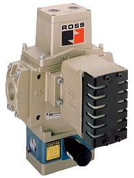




Double Valves with Electro-Pneumatic E-P Monitor SERPAR® 35 Series
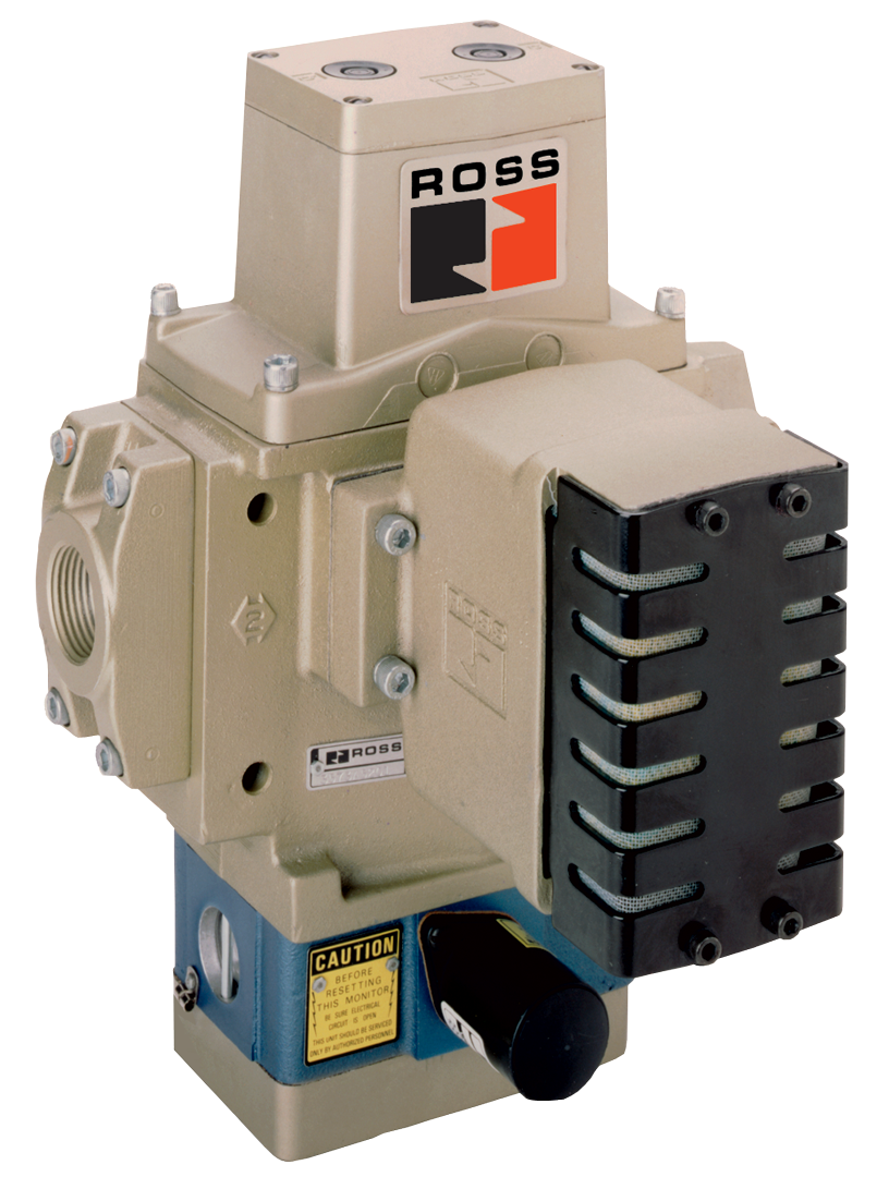
 Product Catalog
Product Certification - CSA
Product Catalog
Product Certification - CSA
- Internal monitoring – requires no additional monitoring circuitry
- Automatic lock-out/inhibit upon detection of a malfunction
- Default to de-energized position upon fault detection
- Dedicated reset function
- No undesired automatic reset upon removal of electrical or pneumatic energy sources
- Built-in non-clogging silencers
Double Valves with Electro-Pneumatic E-P Monitor SERPAR® 35 Series Product Overview
The SERPAR® Series valves are internally monitored double valves with a built-in monitoring device that checks for the proper operation of each valve element. If the internal monitor detects a valve fault on a particular cycle, the double valve will fail to a safe condition (all downstream air is exhausted) and the monitor will lock-out to inhibit further operation of the device.
Normal operation can only be resumed by a momentary reset signal to the valve. Valve models with E-P monitor are available with Single Input Signal and Dual Input Signal. Single Input valves require only one main solenoid signal wired into the terminal strip of the E-P monitored double valve. The main solenoid signal is wired into terminal 1 and internally jumpered to the second main solenoid. Commons are wired into terminal 3. This allows both solenoids to be energized and de-energized simultaneously for proper valve operation.
Dual Input valves require two solenoid signals wired independently into the terminal strip of the E-P monitored double valve. One main solenoid signal is wired into terminal 1 and the second main solenoid signal is wired into terminal 5. Commons are wired into terminal 3. Both solenoid signals must arrive simultaneously for proper valve operation.
Please refer to the side and below for links to easily navigate and download Double Valves with Electro-Pneumatic E-P Monitor SERPAR® 35 Series catalogs, installation instructions, and technical data. Additionally, you have the option to filter through all available options to discover the ideal Double Valves with Electro-Pneumatic E-P Monitor SERPAR® 35 Series variant that meets your requirements.
loading...
loading...
Product Overview
The ROSS Controls SERPAR 35 Series Double Valves with Electro-Pneumatic (E-P) Monitor are internally monitored double valves for press clutch/brake control and Category 3 and 4 safety circuits requiring both pneumatic and electrical fault detection in a single valve assembly. Available in Basic Sizes 8, 12, and 30, these valves cover port sizes from 1/2 inch to 2 inches and provide flow coefficients from Cv 3.5 to 21 in-out and up to 43 exhaust.
The E-P monitor combines pneumatic monitoring of the SERPAR Crossflow passages with an electrical switch (SW) wired into the solenoid pilot circuit. When the monitor detects a fault, a pressure imbalance shifts the internal spool, which trips the switch SW, breaking the electrical circuit to both pilot solenoids and allowing both valve elements to return to the closed position. The valve remains locked out until the reset solenoid receives a momentary electrical signal, which resets switch SW and restores the solenoid circuit.
Valve models with E-P monitor are available in two signal configurations. Single Input Signal valves require only one main solenoid signal. This signal is wired to terminal 1 on the integrated terminal strip and is internally jumpered to the second main solenoid; both solenoids energize and de-energize simultaneously from a single control output. Dual Input Signal valves require two independent solenoid signals: one to terminal 1 (Solenoid A) and one to terminal 5 (Solenoid B), with commons on terminal 3. Both signals must arrive simultaneously for proper valve operation.
The E-P monitor's electrical switch provides an additional circuit path to terminal 7, which allows connection of an external lockout indicator (panel light, bell, or other device) through terminals 7 and 3 to notify operators when the valve is in lockout condition. All models use the integrated terminal strip for solenoid, reset, and indicator wiring.
Key Engineering Features
- Electro-Pneumatic Internal Monitoring - Combines pneumatic crossflow pressure monitoring with electrical switch action, providing both pneumatic isolation and solenoid circuit de-energization on a single fault event. No external monitoring hardware is required.
- Single Input and Dual Input Signal Options - Single input models accept one solenoid signal and internally jumper both solenoids, simplifying wiring from press safety controls. Dual input models require two independent simultaneous signals for applications where individual solenoid monitoring is required by the safety specification.
- Solenoid Reset - Reset is accomplished by applying a momentary electrical signal to the reset solenoid terminals (rated for intermittent duty only). Both main solenoids must be de-energized during and after reset to prevent inadvertent press cycling.
- Electrical Lockout Indicator Output - During lockout, terminals 3 and 7 on the terminal strip are connected, enabling a panel indicator light, bell, or other 250-VAC-rated device to be wired through these terminals as a remote lockout notification.
- Integrated Terminal Strip Wiring - All electrical connections (Solenoid A, Solenoid B, commons, reset solenoid, and lockout indicator) are brought to a single terminal strip with nine numbered terminals, simplifying installation and reducing wiring errors.
- SERPAR Crossflow Poppet Construction - Parallel crossflow passages with dual poppet and spool valve elements produce balanced flow paths and limit outlet pressure to below 2% of inlet when one element is open and the other is closed.
- PTFE Backup Piston Rings - Enable operation with or without in-line lubrication, extending service life and reducing filtration and lubrication maintenance requirements.
- Built-In High-Flow Non-Clogging Silencers - Integrated exhaust silencers maintain exhaust Cv ratings across the valve's service life, preventing back pressure buildup that could affect brake engagement timing.
- Manual Override Option - Available with or without manual rubber-grommet overrides for commissioning and troubleshooting individual valve elements without energizing solenoids.
- Category 4, PL e / SIL 3 Certified - Independently certified to Category 4 PL e per ISO 13849-1 and SIL 3 per IEC 62061. DGUV tested and CE marked. SISTEMA library available for download for safety calculations.
Technical Specifications
General Specifications
| Parameter | Specification |
| Valve Function | 3/2 Normally Closed |
| Construction Design | Dual Poppet with SERPAR Crossflow passages |
| Actuation | Solenoid Pilot Controlled (two solenoids, rated for continuous duty) |
| Monitoring | Internal Electro-Pneumatic (E-P) Monitor |
| Signal Input Options | Single Input Signal or Dual Input Signal (both available) |
| Reset | Solenoid reset (intermittent duty rating); momentary electrical signal required |
| Mounting | Inline with piping flanges; preferably vertical with pilot solenoids on top |
| Basic Sizes Available | 8, 12, 30 |
| Port Sizes (In/Out) | 1/2", 3/4", 1", 1-1/4", 1-1/2", 2" (2" on Size 30 requires 1999H77 flange kit) |
| Thread Options | NPT (no prefix) and G/BSPP (D prefix) |
| Operating Pressure | 30 to 125 psig (2.1 to 8.5 bar) |
| Flow Media | Filtered air; 5-micron filtration recommended |
| Valve Body Material | Cast Aluminum |
| Poppet Material | Acetal and Stainless Steel |
| Seal Material | Buna-N |
| Minimum Operation Frequency | At least once per month |
| Functional Safety Data | Category 4, PL e; B10D: 20,000,000; PFHD: 7.71x10⁻⁹; MTTFD: 301.9 years (nop: 662,400) |
| Safety Integrity Level | SIL 3 per IEC 62061:2001 |
| Enclosure Rating | IP65 per IEC 60529 |
| Electrical Connection | Terminal strip with 9 terminals (Solenoid A, B, common, reset solenoid, lockout indicator) |
Temperature Ratings
Temperature ratings apply to all E-P monitor configurations in Basic Sizes 8, 12, and 30.
| Configuration | Ambient Temperature | Media Temperature |
| All Sizes - Ambient | 40 to 120F (4 to 50C) | 40 to 175F (4 to 80C) |
Important: At media temperatures near 40F (4C), compressed air must be free of water vapor to prevent ice formation inside valve passages that could alter monitoring response.
Electrical Data (Solenoid Pilot Valves)
Main solenoids rated for continuous duty. Reset solenoid rated for INTERMITTENT DUTY only. Prolonged continuous energization of the reset solenoid will cause burnout and disable the reset function. E-P monitor reset solenoid voltages: 24-48 VDC or 100-120 VAC/DC.
| Voltage | Power Consumption |
| 24 VDC (Main solenoids) | 14 watts per solenoid |
| 110-120 VAC, 50/60 Hz (Main solenoids) | 87 VA inrush, 30 VA holding per solenoid |
| 230 VAC, 50/60 Hz (Main solenoids) | 87 VA inrush, 30 VA holding per solenoid (not available in US) |
| 24-48 VDC (Reset solenoid) | Intermittent duty rated |
| 100-120 VAC/DC (Reset solenoid) | Intermittent duty rated |
Flow Performance Data
Flow data for SERPAR 35 Series E-P Monitor, Basic Sizes 8, 12, and 30. Response time: T(msec) = M + F x V. Data applies to both Single Input and Dual Input signal models.
| Basic Size | Port Size (In-Out) | Cv (In-Out) | Cv (Out-Exhaust) | M (msec) | F (1-2) | F (2-3) | Weight lb (kg) |
| 8 | 1/2" | 3.5 (3400 Nl/min) | 8.5 (8400 Nl/min) | 15 | 0.70 | 0.30 | 11.8 (5.3) |
| 8 | 3/4" | 4.0 (3900 Nl/min) | 12 (12000 Nl/min) | 15 | 0.65 | 0.23 | 11.8 (5.3) |
| 12 | 3/4" | 8.0 (7900 Nl/min) | 15 (15000 Nl/min) | 15 | 0.65 | 0.23 | 15.5 (7.0) |
| 8 | 1" | 4.0 (3900 Nl/min) | 12 (12000 Nl/min) | 20 | 0.33 | 0.21 | 11.8 (5.3) |
| 12 | 1" | 8.5 (8400 Nl/min) | 19 (19000 Nl/min) | 20 | 0.28 | 0.21 | 15.5 (7.0) |
| 12 | 1-1/4" | 9.0 (8900 Nl/min) | 21 (21000 Nl/min) | 20 | 0.28 | 0.21 | 15.5 (7.0) |
| 30 | 1-1/4" | 20 (20000 Nl/min) | 42 (41000 Nl/min) | 25 | 0.19 | 0.07 | 35.0 (15.8) |
| 30 | 1-1/2" | 21 (21000 Nl/min) | 43 (42000 Nl/min) | 25 | 0.18 | 0.07 | 35.0 (15.8) |
Response Time Formula: Valve Response Time (msec) = M + F x V, where M is the average time constant for valve element movement, F is the fill/exhaust factor in msec per cubic inch of downstream volume, and V is the volume in cubic inches.
Certifications & Compliance
| Certification/Standard | Detail |
| Functional Safety - Category | Category 4, Performance Level e per ISO 13849-1:2015, the highest level for control-reliable pneumatic safety valves. |
| Safety Integrity Level | SIL 3 per IEC 62061:2001. |
| Reliability Data | B10D: 20,000,000 cycles; PFHD: 7.71x10⁻⁹; MTTFD: 301.9 years (nop: 662,400 operations per year). |
| DGUV | DGUV certified for German and European occupational safety requirements. |
| CE Marking | CE marked for applicable EU directives including the Machinery Directive. |
| Declaration of Conformity | Certificate of Compliance for all SERPAR 35 Series E-P monitor configurations. |
| SISTEMA Library | SISTEMA Library files available for download from rosscontrols.com to support ISO 13849-1 safety function calculations. |
| OSHA Compliance | Designed to satisfy OSHA 29 CFR 1910.217 requirements for mechanical power presses with pneumatically controlled clutch and brake mechanisms. |
| Enclosure Protection | IP65 per IEC 60529 / DIN 40050. |
Typical Applications & Industries
Mechanical Press Clutch/Brake Control with PLC Integration
- Stamping press clutch/brake control where the press safety PLC requires an electrical confirmation signal from the valve monitor before issuing each stroke command. The E-P monitor's terminal strip provides direct wiring of the lockout indicator circuit to the PLC input module.
- High-speed progressive die press operations where the E-P monitor's solenoid reset function allows the safety PLC to command a controlled valve reset sequence rather than requiring an operator to physically access a reset button or air valve.
- Multi-press automated transfer line control where the same safety PLC signal initiates both solenoid reset (via the reset solenoid terminal) and solenoid actuation, allowing a coordinated line restart sequence after a press fault.
- Dual-input press control systems where two independent safety channels from a dual-channel safety relay output control Solenoid A (terminal 1) and Solenoid B (terminal 5) independently, satisfying Category 4 monitoring requirements for each solenoid channel separately.
Press Energy Isolation and Safety Gate Control
- Pneumatic energy isolation systems on press lines where the lockout indicator terminals are wired to the machine safety system to signal when the double valve has locked out and air energy has been isolated from downstream press circuits.
- Safety gate and light curtain interlock systems where the E-P monitor's single-input configuration accepts a single safety relay output to simultaneously de-energize both valve solenoids on a safety stop command.
- Press die change safety circuits where the E-P monitored double valve controls pneumatic cylinder clamping and hold-down systems, with the lockout indicator wired to the die change control panel to verify valve status before die removal.
Large Tonnage Press and Forging Applications
- Large-tonnage mechanical press and forging hammer clutch/brake control where Size 30 valves with 1-1/4 to 2-inch ports (Cv 20 to 21 in-out, Cv 42 to 43 exhaust) are required for adequate response times on large clutch/brake actuator volumes.
- Transfer press and tandem line control where each press station's clutch/brake circuit includes an E-P monitored double valve whose lockout indicator output feeds a central press line safety PLC monitoring all stations simultaneously.
- Hydraulic-pneumatic combination press systems where the pneumatic clutch/brake E-P monitored valve provides electrical status signals compatible with the hydraulic safety system's monitoring architecture.
Safety-Certified Machine Export and European CE Compliance
- Press equipment exported to European markets where CE marking requires Category 4 press control valves with DGUV certification and documentation supporting EN ISO 13849-1 safety calculations using SISTEMA.
- Customer projects requiring documented PFHd and MTTFd values for press clutch/brake safety function calculations, where the E-P monitor's published B10D = 20,000,000 and PFHD = 7.71x10⁻⁹ provide the necessary reliability data.
- New press installations in facilities with existing safety PLC infrastructure where the E-P monitor's solenoid reset via terminal strip simplifies integration with the plant safety system's fault handling and reset sequences.
Ordering and Model Number Configuration
SERPAR 35 Series E-P Monitor valves use the standard 35-series model number format. Signal type (single or dual input), override option, port size, and basic size are encoded in the model number.
|
SERPAR 35 Series E-P Monitor Model Number Structure:
3573 A 5141 W | 3573 Rev Port Voltage Level Code
Port Code - Single Input Signal, With Manual Overrides: 4141 = Size 8, 1/2" 5141 = Size 8, 3/4" 5151 = Size 12, 3/4" 6151 = Size 8, 1" 6161 = Size 12, 1" 7161 = Size 12, 1-1/4" 7151 = Size 30, 1-1/4" 8161 = Size 30, 1-1/2"
Port Code - Single Input Signal, Without Overrides: 4161 = Size 8, 1/2" 5161 = Size 8, 3/4" 5171 = Size 12, 3/4" 6171 = Size 8, 1" 6181 = Size 12, 1" 7181 = Size 12, 1-1/4" 7171 = Size 30, 1-1/4" 8181 = Size 30, 1-1/2"
Port Code - Dual Input Signal, With Manual Overrides: 4341 = Size 8, 1/2" 5341 = Size 8, 3/4" 5351 = Size 12, 3/4" 6351 = Size 8, 1" 6361 = Size 12, 1" 7361 = Size 12, 1-1/4" 7351 = Size 30, 1-1/4" 8361 = Size 30, 1-1/2"
Thread: Blank = NPT, D prefix = G (BSPP) Voltage: W = 24 VDC, Z = 110-120 VAC 50/60 Hz, Y = 230 VAC (not in US)
Example: 3573A5141W = Size 8, 3/4", single input, with overrides, 24 VDC Example: D3573A8361Z = G thread, Size 30, 1-1/2", dual input, with overrides, 120 VAC |
Single Input Signal models (port codes ending in -1xx series) require one main solenoid output from the safety controller. Dual Input Signal models (port codes ending in -3xx series) require two independent simultaneous solenoid outputs.
The 2-inch port size for Size 30 requires ordering a separate 1999H77 piping flange kit and using the replacement valve without flanges model number.
The reset solenoid is rated for INTERMITTENT DUTY ONLY. Do not energize continuously. Apply as a momentary signal only. Continuous energization causes burnout and loss of reset capability.
Connectors must be ordered separately; the terminal strip wiring connections are made directly to the integrated terminal strip on the valve body.
Voltage code Y (230 VAC) is not available in the United States per OSHA press control voltage limits.
For replacement valve bodies without piping flanges: Single Input with overrides (3573A4201W/Z/Y), Single Input without overrides (3573A4221W/Z/Y), Dual Input with overrides (3573A4301W/Z/Y), Dual Input without overrides (3573A4321W/Z/Y) for Size 8. Size 12 uses 5xxx prefix; Size 30 uses 7xxx prefix.
Accessories
Piping Flange Kits (Connection Piping Kits)
All required seals and mounting bolts for two flanged connections. Same piping flange kits as SERPAR L-G monitor series.
| Port Size | Basic Size | NPT Kit | G Kit |
| 1/2" | 8 | 661K77 | D661K77 |
| 3/4" | 8 | 662K77 | D662K77 |
| 3/4" | 12 | 664K77 | D664K77 |
| 1" | 8 | 663K77 | D663K77 |
| 1" | 12 | 665K77 | D665K77 |
| 1-1/4" | 12 | 666K77 | D666K77 |
| 1-1/4" | 30 | 667K77 | D667K77 |
| 1-1/2" | 30 | 668K77 | D668K77 |
Downstream Pressure Monitoring Switches
Factory-preset pressure switches for energy release verification downstream of the valve, preset to 5 psi (0.3 bar) falling. Model 586A86 with DIN EN 175301-803 Form A, 1/8 NPT. Redundant dual assembly RC026-13 also available.
Lockout Indicator Wiring
During lockout, terminals 3 and 7 on the E-P monitor terminal strip are connected. Customer can wire a panel indicator light, audible alarm, or input to the safety PLC through terminals 7 and 3. Device voltage must not exceed 250 VAC or 30 VDC. This circuit is for indication only and does not affect valve function.
Related Products & Accessories
- SERPAR 35 Series L-G Monitor, 1/2 to 2" (Series 183) - Pneumatic-only L-G monitored version; pneumatic reset option available instead of solenoid reset. https://www.rosscontrols.com/en/series/183-double-valves-with-pneumatic-l-g-monitor-ports-1-2-to-2
- SERPAR 35 Series L-G Monitor, 3/8 to 3/4" (Series 184) - L-G monitored double valves for smaller port sizes. https://www.rosscontrols.com/en/series/184-double-valves-with-pneumatic-l-g-monitor-ports-3-8-to-3-4
- DM2 Series D (Series 52) - Self-monitored double valve with total dynamic monitoring and complete memory. https://www.rosscontrols.com/en/series/52-double-valves-for-clutch-brake-control
- CrossFlow 35 Series, 3/8 to 1-1/2" (Series 181) - Externally monitored double valves with pressure switches for customer-supplied monitoring. https://www.rosscontrols.com/en/series/181-double-valves-with-pressure-switches-ports-3-8-to-1-1-2
- Piping Flange Kits (Series 2839) - Connection piping kits for inline mounting of SERPAR and CrossFlow double valves. https://www.rosscontrols.com/en/series/2839-piping-flange-kits
- L-O-X Lockout Valves - Energy isolation lockout valves for pneumatic system lockout/tagout. https://www.rosscontrols.com/en/series/1287-lockout-valves-15-series
Frequently Asked Questions (FAQ)
Q: What is the functional difference between single input and dual input E-P monitor valves?
A: Single Input valves accept one main solenoid signal wired to terminal 1. This signal is internally jumpered to the second main solenoid so both solenoids energize and de-energize from a single safety relay output. Dual Input valves require independent simultaneous signals to terminal 1 (Solenoid A) and terminal 5 (Solenoid B). Dual input is used when the safety system architecture requires independent monitoring of each solenoid channel, such as in a dual-channel safety relay configuration.
Q: Why is the reset solenoid rated for intermittent duty only?
A: The reset solenoid operates an internal mechanism that must move and return; sustained energization would hold the mechanism in a state that does not benefit reset function and generates heat. Prolonged energization leads to solenoid burnout, which permanently disables the reset capability until the solenoid is replaced. Apply the reset signal as a momentary pulse only.
Q: What is the lockout indicator circuit (terminals 3 and 7)?
A: During lockout, the E-P monitor switch SW shifts, connecting terminals 3 and 7 on the terminal strip. An indicator light, horn, or PLC input wired through these terminals receives a signal whenever the valve is in the locked-out state. This circuit carries no load beyond what the customer's indicator requires and must not exceed 250 VAC or 30 VDC. It does not affect valve operation.
Q: How does the E-P monitor detect a valve fault?
A: The SERPAR Crossflow passages create equal monitoring pressure signals at both ends of the E-P monitor spool when both valve elements operate synchronously. If one element is open and the other is closed, the open element's crossflow passage delivers full inlet pressure to one end of the spool while the closed element's passage provides near-zero pressure at the other end. This imbalance shifts the spool, trips switch SW, breaks the solenoid circuit, and allows both elements to close.
Q: Can the E-P monitor reset be automated by the press control PLC?
A: Yes. The reset solenoid terminals are accessible on the integrated terminal strip. The press control PLC or safety relay can issue a momentary pulse to the reset solenoid output to execute a controlled valve reset as part of a press restart sequence. Both main solenoids must be de-energized before and during reset to prevent inadvertent valve actuation after reset.
Q: Is the E-P monitor suitable when the press control system already has an external monitoring device?
A: Yes, the E-P monitor is self-contained and does not require external monitoring hardware, but can work alongside external monitoring systems. For presses where external monitoring is preferred over internal monitoring, the CrossFlow 35 Series with pressure switches (Series 181 or 182) is the appropriate alternative, providing pressure switch feedback to an external monitoring device.
Q: What safety certifications apply to the SERPAR 35 Series E-P monitor?
A: Category 4, PL e per ISO 13849-1:2015; SIL 3 per IEC 62061:2001; DGUV tested; CE marked; B10D = 20,000,000 cycles; PFHD = 7.71x10⁻⁹; MTTFD = 301.9 years. SISTEMA library available from rosscontrols.com for ISO 13849-1 safety calculations.
Q: What port sizes are available and which basic size corresponds to each?
A: Port size 1/2 and 3/4 inch: Basic Size 8 (Cv 3.5 to 4.0 in-out). Port size 3/4 and 1 inch: also Size 12 at Cv 8.0 to 8.5 in-out. Port size 1 and 1-1/4 inch: Size 12 at Cv 8.5 to 9.0 in-out. Port size 1-1/4 and 1-1/2 inch: Size 30 at Cv 20 to 21 in-out. Port size 2 inch: Size 30 only, requires separate 1999H77 flange kit.
Q: What happens to outlet pressure when the E-P monitor detects a fault?
A: When the monitor spool shifts on fault detection, the electrical circuit to both pilot solenoids is broken, allowing both valve elements to return to their normally closed position. Outlet pressure drops below 2% of inlet pressure during the crossflow imbalance phase and exhausts to atmosphere as both elements close. The valve remains locked out until a momentary reset solenoid pulse is applied with both main solenoids de-energized.
Q: How often must the valve be cycled for proper function verification?
A: At minimum once per month. This periodic cycling verifies that all valve elements, the E-P monitor spool, and switch SW are free to move and that the monitoring function operates correctly.
Q: Are SERPAR E-P monitor valves compatible with the same piping flange kits as L-G monitor valves?
A: Yes. The same piping flange kits (661K77 through 668K77) are used for both L-G monitor and E-P monitor SERPAR 35 Series valves of the same basic size and port size. This allows a valve to be changed between L-G and E-P monitor types without modifying the piping installation.
Q: What wiring procedure should be followed during E-P monitor reset?
A: Before initiating reset: (1) Remove electrical signals from both main solenoids (terminals 1 and 5 for dual input, terminal 1 for single input). (2) Apply a momentary pulse to the reset solenoid terminals. (3) Wait for reset confirmation. (4) Only after reset is confirmed and the cause of the lockout has been corrected, reapply the main solenoid signals as required. Failure to de-energize main solenoids before reset can cause immediate valve actuation, creating a hazardous press stroke.
Installation & Maintenance Guidelines
- Mount the valve vertically with pilot solenoids pointing upward as the preferred orientation.
- Install 5-micron filtration upstream to protect crossflow passages and poppet surfaces.
- Verify piping flanges are installed with all seals and mounting bolts before commissioning.
- Wire the terminal strip per the published Single Input or Dual Input wiring diagram. Terminal 1 is Solenoid A input; terminal 3 is common; terminal 5 is Solenoid B input (dual input only); terminal 7 is lockout indicator; reset solenoid wired to the reset terminals.
- For Single Input configuration, Solenoid B is internally jumpered. Wire only terminal 1 (solenoid input) and terminal 3 (common) for the main solenoid signal.
- Connect the lockout indicator circuit (terminals 7 and 3) to a panel indicator or PLC input. Do not connect devices exceeding 250 VAC or 30 VDC to these terminals.
- Apply the reset solenoid signal as a momentary pulse only. Do not latch or hold the reset solenoid signal active. Continuous energization causes burnout.
- Ensure both main solenoids are de-energized before and during reset. Issuing reset with one or both solenoids energized will cause the valve to actuate immediately after reset, producing a potentially hazardous machine stroke.
- After installation, perform at minimum 10 complete actuation cycles to verify clean shifting, absence of false E-P monitor trips, and proper lockout indicator operation.
- Investigate and correct the root cause of any lockout event before performing reset.
Warranty & Global Support
ROSS Controls provides a one-year warranty on all SERPAR 35 Series products, covering defects in material and workmanship from date of purchase.
Global technical support available through ROSS offices in USA, Canada, Brazil, Germany, France, United Kingdom, India, China, and Japan.
Contact ROSS Controls USA at +1-248-764-1800 or Technical Service at 1-888-TEK-ROSS (835-7677), or visit rosscontrols.com.
SISTEMA library files, dimensional drawings, and response time charts available at rosscontrols.com or by contacting ROSS Controls at (800) GET-ROSS (438-7677).
Download Catalog: https://www.rosscontrols.com/en/series/186-double-valves-with-electro-pneumatic-e-p-monitor
Download Documents
Double Valves with Electro-Pneumatic E-P Monitor