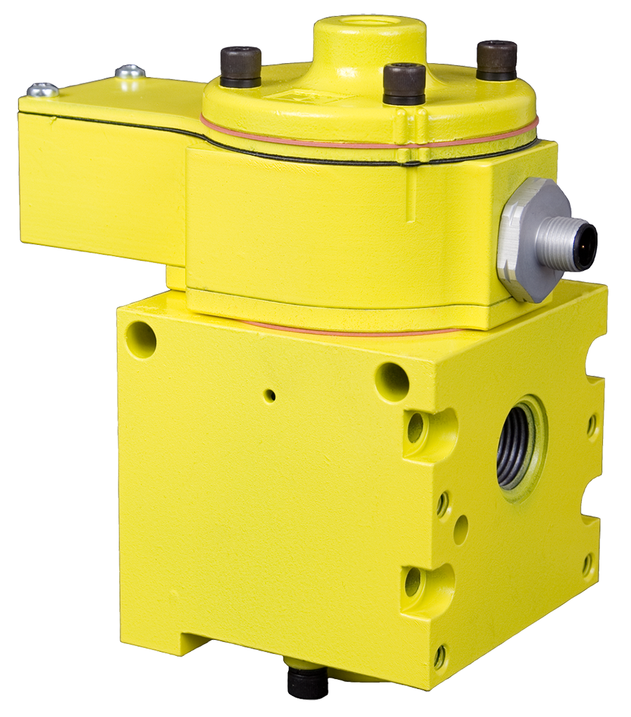
SV27 Series Pilot Operated Check Valves for External Monitoring Safety Category 2 PL c
- Dirt tolerant, wear compensating for quick response and high flow capacity
- Poppet construction for near zero leakage & dirt tolerance
- Senses internal position & state
- Electrical feedback via DPST switch (Double-Pole Single-Throw)
- Directly operated safety-rated force-guided positive-break status switch (DPST)
- A diagnostic coverage (DC) of up to 90% can be obtained by monitoring the safety switch status
- SISTEMA Library available for download
SV27 Series Pilot Operated Check Valves for External Monitoring Product Overview
Pilot Operated Check valves are designed to trap pressure in order to hold a cylinder in place when a safety event occurs. The SV27 Series Sensing Valve uses a safety-rated DPST switch to monitor the valve's operating position. The SV27 PO Check valves can be used for load holding functions in Category 2 (single) or Category 3 (redundant) applications with proper integration and monitoring. The feedback switch informs the controls that the valve internals have shifted properly.
Please refer to the side and below for links to easily navigate and download ROSS Controls SV27 Series Pilot Operated Check Valves for External Monitoring catalogs, installation instructions, and technical data. Additionally, you have the option to filter through all available options to SV27 Series Pilot Operated Check Valves for External Monitoring variant that meets your requirements.
loading...
loading...
Product Overview
The ROSS Controls SV27 Series Pilot Operated Check Valves for External Monitoring are single-channel load holding valves designed to trap pressure in a cylinder or pneumatic actuator to maintain a safe position when a safety event occurs. The SV27 Series builds on the proven ROSS 27 Series poppet platform by integrating a safety-rated DPST (Double-Pole Single-Throw) position switch directly into the valve body. This switch monitors the valve's internal operating position and provides electrical feedback to a customer-supplied safety controller, enabling active external monitoring of the valve state.
The integrated DPST switch is a directly operated, force-guided, positive-break safety switch that activates based on the physical position of the valve internals. When the safety switch output is monitored by a safety controller, a diagnostic coverage (DC) of up to 90 percent can be obtained. This DC level supports integration into safety circuits up to Category 2, Performance Level c (PL c) per ISO 13849-1 in single-valve applications, and up to Category 3 in redundant configurations with proper integration.
The SV27 Series is available in solenoid pilot controlled (24 VDC or 110/120 VAC) and pressure-controlled (normally closed) configurations. Port sizes include 1/2" and 3/4", with NPT or G (BSPP) thread options. Electrical connection uses CNOMO connectors. The cast aluminum body with acetal and stainless steel poppets provides high flow capacity, near-zero leakage, and long service life in industrial environments including automotive press lines, metal forming operations, and assembly automation.
The SV27 Series carries DGUV certification, CE marking, CSA/UL certification, and EAC declaration of conformity, making it suitable for North American, European, and international market installations. The SISTEMA library is available for download to support ISO 13849-1 safety calculations.
Key Engineering Features
- Integrated DPST Safety Switch for External Monitoring - A directly operated, safety-rated DPST (Double-Pole Single-Throw) switch monitors the valve's internal position. Both NO and NC switch contacts provide dual-channel feedback to the safety controller, enabling up to 90% diagnostic coverage for Category 2 safety applications.
- Category 2 PL c Safety Capability - In single-valve application with proper monitoring of the DPST switch, the SV27 achieves Safety Category 2, PL c per ISO 13849-1. In redundant configurations with two SV27 valves and proper integration, Category 3 PL e performance is achievable.
- Force-Guided Positive-Break DPST Switch - The DPST switch uses a force-guided positive-break mechanism that directly actuates from the valve spool or poppet position. This design prevents contact welding from disabling fault detection, ensuring the switch accurately reports valve state even after years of service.
- 90 Percent Diagnostic Coverage - Monitoring both NO and NC switch contacts of the DPST switch with all changes in valve state achieves up to 90 percent diagnostic coverage (DC), satisfying the requirements for Category 2 safety functions and supporting PL c performance level calculations in SISTEMA.
- ROSS Poppet Technology - Dirt-tolerant, wear-compensating poppet construction provides near-zero leakage, high flow capacity, quick response, and long service life. The self-cleaning poppet seat maintains sealing performance in contaminated industrial air environments.
- Solenoid or Pressure Control Options - Available in solenoid pilot controlled (24 VDC or 110/120 VAC) for PLC-integrated control, and pressure controlled for purely pneumatic circuits without electrical signals. Both configurations integrate the same DPST safety switch for position feedback.
- High Flow Capacity - The 3/4" body size achieves flow up to 8.3 Cv (8,167 Nl/min), supporting high-cycle cylinder circuits that require rapid extend and retract times while still providing reliable load holding and position monitoring.
- DGUV, CE, CSA/UL, and EAC Certifications - DGUV certification (Sicherheit gepruft), CE marking for the EU Machinery Directive, CSA/UL certification for North American markets, and EAC declaration make the SV27 suitable for global safety-critical installations without additional certification steps.
- CNOMO Electrical Connector - CNOMO (standard industrial mini connector) electrical connection is used for both solenoid and switch wiring. Pre-wired cable assemblies are available to simplify panel wiring and reduce field assembly time.
- SISTEMA Library Available - Downloadable SISTEMA library files support ISO 13849-1 PL calculations, providing pre-validated safety data blocks for the SV27 that can be imported directly into SISTEMA for safety circuit documentation.
Technical Specifications
General Specifications
| Parameter | Specification |
| Series | SV27 |
| Valve Function | 2/2 Pneumatic Pilot Operated Check (PO Check) |
| Default State | Normally Closed (check active) |
| Construction | Poppet |
| Actuation | Electrical (Solenoid Pilot) or Pneumatic (Pressure Controlled) |
| Mounting | Inline |
| Body Size | 3/4" |
| Port Sizes Available | 1/2", 3/4" |
| Thread Types | NPT and G (BSPP) |
| Pressure Release Type | DPST Switch (electrical position feedback) |
| Operating Pressure | 40 to 150 psig (2 to 10 bar) |
| Voltage (Solenoid Models) | 24 VDC or 110/120 VAC |
| Power Consumption (24 VDC) | 6 watts |
| Power Consumption (110/120 VAC) | 87 VA inrush, 30 VA holding |
| Electrical Connection | CNOMO (standard industrial mini connector) |
| DPST Switch Rating | 2.5 A / 120 VAC maximum; 50 mA / 24 VDC minimum |
| Flow Media | Filtered Air (5-micron recommended) |
| Valve Body Material | Cast Aluminum |
| Poppet Material | Acetal and Stainless Steel |
| Seal Material | Buna-N; Fluorocarbon |
| Diagnostic Coverage | Up to 90% DC (via monitoring of both DPST switch contacts) |
| B10D Value | 20,000,000 cycles |
| MTTFD | 98.15 years (at 7,360 cycles/year) |
| PFHD | 2.35 x 10^-8 per hour |
Temperature Ratings
Temperature ratings apply to all SV27 Series single-valve configurations. Media must be filtered to 5-micron or finer to maintain poppet seat integrity.
| Configuration | Ambient Temperature | Media Temperature |
| All SV27 Single Valve Variants (Buna-N and Fluorocarbon seals) | 40 to 120 F (4 to 50 C) | 40 to 175 F (4 to 80 C) |
Electrical Data (Solenoid Pilot Valves)
Solenoid pilot models are rated for continuous duty. Both DPST switch contacts (NO and NC) must be monitored by the safety controller to achieve 90% diagnostic coverage.
| Voltage | Power Consumption |
| 24 VDC | 6 watts (continuous duty) |
| 110/120 VAC, 50/60 Hz | 87 VA inrush, 30 VA holding |
Flow Performance Data
Flow performance data for SV27 Series single-valve representative variants. Flow is rated for the 1-2 (free flow) direction; pilot-opened reverse flow capacity is equivalent in the DPST-unlocked state.
| Model | Port 1 Size | Port 2 Size | Ports 1-2 Flow | Length | Width | Height | Weight | Voltage |
| SV27NC115408CSAA1A | 1/2" NPT | 1/2" NPT | 4.5 Cv (4,428 Nl/min) | 5.0 in (127 mm) | 3.3 in (84 mm) | 8.5 in (215 mm) | 5.0 lb (2.3 kg) | 110/120 VAC |
| SV27DC115508CSAA1A | 3/4" G (BSPP) | 3/4" G (BSPP) | 8.3 Cv (8,167 Nl/min) | 5.0 in (127 mm) | 3.3 in (84 mm) | 8.5 in (215 mm) | 5.0 lb (2.3 kg) | 110/120 VAC |
Certifications & Compliance
| Certification/Standard | Detail |
| Safety Category / PL Rating | Category 2, Performance Level c (PL c) per ISO 13849-1 in single-valve application with proper external monitoring of both DPST switch contacts. Category 3 achievable in redundant configurations. |
| Safety Integrity Level | SIL 2 per IEC 61508 and IEC 61511 (singular application); SIL 3 in redundant configurations with HFT greater than or equal to 1. |
| B10D Value | 20,000,000 cycles, providing the statistical basis for safety lifetime calculations in SISTEMA and other functional safety tools. |
| MTTFD | 98.15 years at 7,360 cycles per year, representing the mean time to dangerous failure for integration into PL calculations. |
| PFHD | 2.35 x 10^-8 per hour, the probability of dangerous failure per hour for use in SIL and PL calculations. |
| Diagnostic Coverage | Up to 90% DC when both NO and NC switch contacts are monitored by the safety controller with all changes in valve control state. |
| DGUV Certification | Yes - DGUV certified (Sicherheit gepruft / tested safety), the German Social Accident Insurance certification confirming the valve meets European safety machinery requirements. |
| CE Marking | Yes - CE marking for conformity with the EU Machinery Directive 2006/42/EC, authorizing sale and installation throughout the European Economic Area. |
| CSA/UL Certification | Yes - CSA/UL certified for the North American market, enabling installation in Canadian and US facilities requiring listed components. |
| EAC Declaration | Yes - EAC conformity declaration for markets requiring Eurasian Economic Union certification. |
| Enclosure Protection | IP65, providing dust-tight protection and resistance to low-pressure water jets for industrial environments. |
Typical Applications & Industries
Automotive Press Lines and Metal Forming
- Solenoid-controlled load holding on pneumatic cylinders in automotive body press lines where Category 2 monitoring confirms the valve has reached the safe-hold state before the press operator enters the die area.
- Metal stamping and deep draw press operations where the SV27 traps die cushion and binder cylinder pressure during die changes, with the DPST switch confirming safe-hold to the press safety controller.
- Roll forming and coil handling equipment where cylinders hold strip tension or guide position during strip breaks and web threading, requiring both load holding and position confirmation to resume automatic operation.
- Transfer die systems where multiple cylinders must hold workpiece position simultaneously, and the DPST switch feedback confirms each axis is in the safe-hold state before the die transfer begins.
Injection Molding and Plastics Processing
- Injection molding machine clamp cylinder circuits where the SV27 traps pressure to hold mold closed, with DPST switch feedback confirming the hold state to the machine controller before injection is initiated.
- Mold change operations where the SV27 enables safe opening of the mold only after confirmation that all hold cylinders have released, reducing the risk of mold damage or operator injury during change-over.
- Blow molding and thermoforming machines where parison or sheet cylinders must hold position during the forming dwell, with monitored load holding ensuring dimensional consistency.
Assembly Automation and Material Handling
- Automated assembly fixtures where cylinder position must be confirmed safe before an operator enters the fixture area, using the DPST switch output to interlock the guard door with the cylinder hold confirmation.
- Vertical lift tables, scissor lifts, and work positioners in assembly lines where the SV27 holds the platform at working height with position feedback integrated into the emergency stop circuit.
- Palletizers, depalletizers, and high-bay storage systems where load-carrying cylinders must confirm safe-hold state before robotic or manual retrieval operations are permitted.
- Conveyor diverters, pushers, and indexing units where the SV27 holds a stop or gate position and reports status to the machine controller, enabling fault detection on valve failure before production continues.
Hazardous and Regulated Industry Applications
- Pharmaceutical manufacturing equipment where monitored pneumatic cylinder position holding is required to confirm safe machine state before operator access to sterile or pressurized zones.
- Food and beverage processing machinery where wash-down environments and hygiene requirements demand sealed valve construction, and Category 2 monitoring satisfies regulatory safety circuit requirements.
- Explosive atmosphere adjacent areas (non-ATEX zones) where the DPST switch feedback replaces proximity sensors that would require ATEX certification, simplifying the safety architecture.
- CE-marked machine exports to the European Economic Area where both the Category 2 safety function and the CE marking on the valve component itself are required to satisfy Machinery Directive documentation.
Ordering and Model Number Configuration
The SV27 Series model number encodes the actuation type, port configuration, body size, voltage, electrical connection, and monitoring configuration. Contact ROSS Controls at (800) 438-7677 or visit rosscontrols.com for the full configurator and current pricing.
|
SV27 Series Single Valve Model Number Structure:
SV27 NC 1 1 5 5 0 8 C S A A 1 A | | | | | | | | | | | Revision Level | | | | | Monitoring Code: 1 = single valve | | | | | Electrical Connection: A = CNOMO | | | | Switch Type: A = DPST | | | | Safety Function: S = Single | | | Connection: C = CNOMO | | | Valve Function: 8 = 2/2 PO Check | | Thread/Seal Code | | Body/Port Size Code | Port Configuration | Pilot Type: 1 = Air Pilot Revision Control Type: NC = Normally Closed (Pressure Controlled); DC = Solenoid Pilot Series: SV27 |
Actuation type: NC = pressure-controlled (normally closed); DC = solenoid pilot controlled (24 VDC or 110/120 VAC).
Voltage codes for solenoid models: 08 = 24 VDC; 07 = 110/120 VAC 50/60 Hz.
Thread types: standard models use NPT threads. G (BSPP) thread variants are designated with 'D' prefix (e.g., D-SV27...).
The SV27 single-valve series is rated Category 2 PL c in single application. For Category 3 PL e, specify the SV27 redundant check valve series (1307).
SISTEMA library files and safety data sheets are available for download at rosscontrols.com.
SV27 Series Single Valve Example Model Numbers
| Model Number | Port Size | Thread | Voltage | Safety Category |
| SV27NC115408CSAA1A | 1/2" NPT | NPT | 110/120 VAC | Category 2 |
| SV27NC115507CSAA1A | 1/2" NPT | NPT | 24 VDC | Category 2 |
| SV27DC115508CSAA1A | 3/4" G | G (BSPP) | 110/120 VAC | Category 2 |
| SV27DC305407CSAA1A | 3/4" NPT | NPT | 24 VDC | Category 2 |
Accessories
CNOMO Electrical Cable Assemblies
Pre-wired CNOMO cable assemblies with flying leads are available in standard lengths for solenoid and DPST switch connections, reducing field wiring time and panel assembly complexity.
Pressure Verification Accessories
Optional pressure verification port accessories include a visual pop-up pin pressure indicator (Model 988A30) and an electrical pressure switch preset at 5 psi falling edge (Model 586A86). These provide additional proof that cylinder pressure has been released before operator access, supporting Category 2 energy verification requirements.
| Accessory | Model | Function |
| Visual Pressure Indicator | 988A30 | Pop-up pin confirms pilot pressure; visual confirmation only |
| Electrical Pressure Switch | 586A86 | Preset 5 psi falling edge; DIN EN 175301-803 Form A connector; electrical feedback to safety controller |
Exhaust Silencers
ROSS aluminum exhaust silencers are available for all SV27 port sizes. Verify silencer flow capacity equals or exceeds the circuit exhaust flow requirements. Contaminated or undersized silencers create backpressure that affects valve shifting speed and diagnostic timing.
L-O-X Lockout Control
The L-O-X manual lockout accessory integrates with the SV27 to provide positive energy isolation for LOTO procedures. The L-O-X mechanism prevents valve re-energization while the lockout device is engaged, enabling zero-energy state verification before maintenance access.
Related Products & Accessories
- 27 Series Pilot Operated Check Valves (1305) - Category 1 PL c inline pilot operated check valves without integrated switch monitoring, for applications where external monitoring is not required. https://www.rosscontrols.com/en/series/1305-27-series-pilot-operated-check-valves
- SV27 Series PO Redundant Check Valves (1307) - Redundant two-valve SV27 assembly for Category 3 PL e load holding with external monitoring - the next safety level above this series. https://www.rosscontrols.com/en/series/1307-sv27-series-pilot-operated-redundant-check-valves
- CC4 Series Double Valve (1303) - 4/3 closed-center double valve for bidirectional safe cylinder control and Category 4 PL e load holding. https://www.rosscontrols.com/en/series/1303-cc4-series-double-valve
- 19 Series Pilot Operated Check Valves (1304) - Compact right-angle Category 1 PL c pilot operated check valves for small-bore circuits and panel mounting. https://www.rosscontrols.com/en/series/1304-19-series-pilot-operated-check-valves
- L-O-X Lockout Valves (Energy Isolation) - Lockout valves for safe energy isolation during maintenance per OSHA lockout/tagout requirements. https://www.rosscontrols.com/en/series/1287-lockout-valves-15-series
- Electrical Connectors - ROSS CNOMO and DIN connector assemblies, prewired cable sets, and lighted indicators for SV27 solenoid and switch wiring. https://www.rosscontrols.com/en/series/91-electrical-connectors
Frequently Asked Questions (FAQ)
Q: What makes the SV27 Series different from the standard 27 Series PO Check Valve?
A: The SV27 integrates a safety-rated DPST (Double-Pole Single-Throw) position switch directly into the valve body. This switch monitors the valve's internal position and provides dual-channel electrical feedback to a customer-supplied safety controller. With proper monitoring of both NO and NC switch contacts, up to 90 percent diagnostic coverage can be achieved, enabling Category 2 PL c safety performance. The standard 27 Series does not include a position switch and achieves only Category 1 PL c.
Q: What safety category and PL does the SV27 single-valve series achieve?
A: In single-valve application with proper monitoring of both DPST switch contacts, the SV27 achieves Safety Category 2, Performance Level c (PL c) per ISO 13849-1 and SIL 2 per IEC 61508/61511. In a redundant configuration (two SV27 valves in series, both monitored), Category 3 PL e is achievable. Refer to series 1307 for the pre-built redundant SV27 configuration.
Q: What is the DPST switch and how does it work?
A: The DPST (Double-Pole Single-Throw) switch is a directly operated, force-guided, positive-break safety switch that physically actuates from the valve spool or poppet position. It has two contacts: one normally open (NO) and one normally closed (NC). When the valve is in its normal operating position, the switch contacts are in their defined states. If the valve fails to reach its commanded position, the switch outputs report the discrepancy to the safety controller. The positive-break design prevents contact welding from masking a fault condition.
Q: What does 90 percent diagnostic coverage mean and how is it achieved?
A: Diagnostic coverage (DC) of 90 percent means that 90 percent of dangerous failure modes within the valve system can be detected by the monitoring scheme. To achieve 90 percent DC with the SV27, both the NO and NC contacts of the DPST switch must be monitored by the safety controller with every change in valve control state. Monitoring only one contact reduces DC. The 90 percent DC value supports Category 2 medium-DC compliance per ISO 13849-1 Table K.1.
Q: What are the voltage options for the SV27 solenoid pilot models?
A: SV27 solenoid pilot models are available in 24 VDC (6 watts) and 110/120 VAC (87 VA inrush, 30 VA holding). Pressure-controlled (normally closed) variants do not use an electrical solenoid but still include the DPST switch for position feedback. Contact ROSS Controls for 230/240 VAC variants.
Q: What certifications does the SV27 hold?
A: The SV27 Series carries: DGUV certification (Sicherheit gepruft, German Social Accident Insurance tested safety), CE marking (EU Machinery Directive 2006/42/EC), CSA/UL certification (North American markets), and EAC declaration of conformity (Eurasian Economic Union). This global certification package makes the SV27 suitable for installations worldwide without additional third-party certification.
Q: What is the MTTFD value for the SV27?
A: The SV27 has an MTTFD of 98.15 years at a usage rate of 7,360 cycles per year. The PFHD is 2.35 x 10^-8 per hour. The B10D value is 20,000,000 cycles. These values are used in SISTEMA and other IEC 62061/ISO 13849-1 calculation tools to determine the achievable performance level for the safety function.
Q: What is the operating pressure range for the SV27?
A: The SV27 single-valve series operates at 40 to 150 psig (2 to 10 bar). The minimum 40 psig requirement reflects the higher operating pressure needed for reliable solenoid pilot shifting and consistent DPST switch actuation. Do not operate below 40 psig.
Q: How is the SV27 used in a Category 2 load-holding circuit?
A: Install the SV27 with port 1 connected to the directional valve (supply side) and port 2 connected to the cylinder port. Connect the solenoid to the safety controller output. Connect both DPST switch contacts (NO and NC) to the safety controller input circuit. When the safety controller commands load holding, it de-energizes the SV27 solenoid and then verifies that both switch contacts confirm the valve has reached the safe-hold state. If the switch does not confirm the state, the controller registers a fault and inhibits machine restart.
Q: How often should the SV27 be tested in load-holding applications?
A: ROSS recommends functional testing of the switch and poppet sealing every 8 hours for load-holding valve applications. This testing frequency is consistent with the ROSS SV27 catalog recommendation and supports the proof test interval assumed in the published safety data. Applications with infrequent load-holding commands should schedule deliberate test cycles at this interval to maintain statistical reliability.
Q: Can the SV27 be used without monitoring the DPST switch?
A: Yes, but without monitoring the DPST switch, the valve functions as a Category 1 PO check valve (equivalent to the standard 27 Series) and the diagnostic coverage drops to 0 percent. To realize the Category 2 PL c safety capability of the SV27, both DPST switch contacts must be actively monitored by the safety controller. Unmonitored switch contacts do not contribute to the safety function.
Q: Is the SV27 available with G (BSPP) threads for European installations?
A: Yes. G (BSPP) thread variants are available for all SV27 configurations. These models are designated with the appropriate thread code in the model number. Contact ROSS Controls at (800) 438-7677 or visit rosscontrols.com for the complete G-thread model number list.
Q: What is the SISTEMA library and how do I access it for the SV27?
A: The SISTEMA library is a set of pre-validated safety component data blocks formatted for import into the SISTEMA (Safety Integrity Software Tool for the Evaluation of Machine Applications) software used for ISO 13849-1 performance level calculations. ROSS provides an SV27-specific SISTEMA library file available for download at rosscontrols.com/en/series/1306. Importing this file eliminates manual data entry of B10D, MTTFD, and PFHD values into SISTEMA.
Installation & Maintenance Guidelines
- Mount the SV27 inline with port 1 connected to the directional control valve side and port 2 connected to the cylinder or actuator port. Incorrect port orientation eliminates the load-holding function.
- Position the valve as close as practical to the cylinder port to minimize the trapped air volume, which reduces cylinder drift distance before pressure equalizes.
- For solenoid pilot models, connect the solenoid to a safety-rated control output that is de-energized when load holding is required. For pressure-controlled models, connect the pilot port to a signal that is removed when load holding is required.
- Connect both DPST switch contacts (NO and NC) to the safety controller input circuit. Monitoring only one contact reduces diagnostic coverage and may not satisfy Category 2 requirements. Use appropriately rated safety input modules.
- Configure the safety controller to verify both DPST switch contacts confirm the expected valve state following every solenoid command change. The controller must register a fault if the switch does not confirm the correct state and must inhibit machine restart until the fault is resolved.
- Supply filtered compressed air at 5-micron or finer filtration upstream of the SV27. The 5-micron filter requirement is specified in the SV27 catalog and is necessary to maintain poppet seat integrity and switch actuation consistency over time.
- Verify supply pressure is within 40 to 150 psig (2 to 10 bar) before commissioning. Pressures below 40 psig may result in incomplete valve shifting and incorrect DPST switch actuation timing.
- Ensure ambient temperature at the installation location is within 40 to 120 F (4 to 50 C). Elevated ambient temperatures above 120 F can affect solenoid coil ratings and switch contact life.
- Perform a DPST switch calibration check during commissioning: energize and de-energize the solenoid at least three times while monitoring both switch contact outputs. Confirm the switch contacts respond correctly and within the expected time after each command. Record the switch response for baseline comparison.
- For load-holding applications, schedule functional testing of the DPST switch and poppet sealing every 8 hours as recommended in the ROSS SV27 catalog. Automated PLC test routines can be programmed to initiate a deliberate load-hold cycle, check switch output, and confirm poppet seal-down.
- If the optional pressure verification accessory is installed, connect the electrical pressure switch (Model 586A86) to the safety controller input. Use the 5 psi falling-edge output to confirm that cylinder pressure has been released to near-zero before permitting operator access.
- Do not restrict the exhaust or blowdown port with undersized silencers. Exhaust back pressure can delay valve shifting and cause the DPST switch to actuate at a different time than expected by the safety controller.
Warranty & Global Support
ROSS Controls provides a one-year warranty on all products, covering defects in material and workmanship from the date of purchase.
Global technical support is available through ROSS offices in the USA (headquarters in Ferndale, Michigan), Canada, Brazil, Germany, France, United Kingdom, India, China, and Japan.
Contact ROSS Controls USA at +1-248-764-1800 or toll-free at (800) 438-7677, or visit rosscontrols.com for product configuration, technical support, and distributor locator services.
For complete technical data, dimensional drawings, SISTEMA library files, DGUV and CE certification documents, and valve configurator access, visit the ROSS Controls SV27 Series product page at rosscontrols.com or contact ROSS at (800) 438-7677.
Download Catalog: https://www.rosscontrols.com/en/documents/381
Download Documents
SV27 Series Pilot Operated Check Valves for External Monitoring
