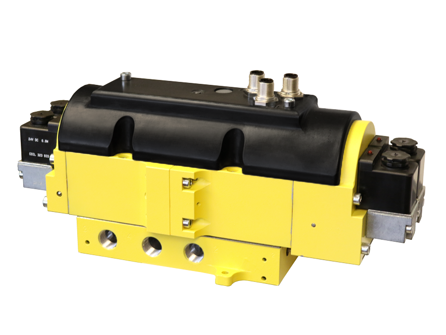
CC4 Series Double Valve Safety Category 4 PL e, External Monitoring
- Redundant control with position feedback - can achieve Category 4, PL e, when used with proper safety controls.
- ROSS poppet technology - fast, reliable, dirt-tolerant, face-sealing, low friction.
- Redundant poppets prevent air from being supplied and exhausted from each outlet port.
- Mid-position sensing using magnetic proximity sensors (PNP) for detection of closed center position providing feedback to the safety control system for external monitoring.
- Dynamic, cyclical, external with customer supplied safety control system. Monitoring should check state of both valve mid-position sensors with any and all changes in state of valve control signal.
- LED indicators on solenoids - aids troubleshooting
- Manual trapped pressure relief to remove stored energy when required
- SISTEMA Library available for download
CC4 Series Double Valve Product Overview
The CC4 Series double valve is a 4/3 safety directional valve, closed center, designed to control the direction of air flow into and out of a double-acting cylinder or other pneumatic actuator in order to drive the cylinder forward or backward to suit the requirements of the machine operation until signaled to shut off and trap pneumatic energy in the cylinder in order to stop cylinder motion (load holding). Thus, reducing the potential hazard of unexpected cylinder motion during employee access for production-related tasks and/or minor servicing.
Turning off all solenoids on the 4/3 CC4 Series valve returns the valve to the center position in order to stop cylinder motion - this also allows jogging of the cylinder. The CC4 Series valve offers this function with the required level of control expected of the machine’s (system’s} safety control system up to Category 4, PL e. Such a control system must be capable of inhibiting further operation of the valve in the event of a fault within the valve.
Please refer to the side and below for links to easily navigate and download ROSS Controls CC4 Series Double Valve catalogs, installation instructions, and technical data. Additionally, you have the option to filter through all available options to CC4 Series Double Valve variant that meets your requirements.
loading...
loading...
Product Overview
The ROSS Controls CC4 Series is a 4/3 safety directional valve with closed center, designed to control the direction of air flow into and out of a double-acting cylinder or other pneumatic actuator. The valve drives a cylinder forward or backward to meet machine operating requirements, then signals shut-off to trap pneumatic energy in the cylinder and stop cylinder motion for load holding. This design reduces the potential hazard of unexpected cylinder motion during employee access for production-related tasks and minor servicing.
When all solenoids on the 4/3 CC4 Series valve are turned off, the valve returns to the center position to stop cylinder motion and permits jogging of the cylinder. The CC4 Series provides this function with the required level of control expected of a safety control system up to Category 4, PL e per ISO 13849-1:2015. The safety control system must be capable of inhibiting further operation of the valve in the event of a fault within the valve.
Built on ROSS poppet technology, the CC4 valve uses a redundant dual poppet construction in a cast aluminum body. Redundant poppets prevent air from being supplied and exhausted from each outlet port simultaneously. Mid-position sensing uses magnetic proximity sensors (PNP type) to detect the closed center position and provide feedback to the safety control system for external monitoring. The valve includes LED indicators on each solenoid and a manual trapped pressure relief function to remove stored energy when required.
The CC4 Series is designed for sub-base mounting in any orientation; horizontal mounting with solenoids on top is preferred. Port sizes range from 1/4 inch to 3/4 inch with NPT or G (BSPP) thread options. Electrical connection uses two 5-pin M12 connectors (IEC 61076-2-101, A-coded) for solenoids and one 5-pin M12 connector for the sensor outputs. The SISTEMA library is available for download to support safety circuit calculations.
Key Engineering Features
- Redundant Dual Poppet Construction - Redundant poppets prevent air from being simultaneously supplied and exhausted from each outlet port, enabling Category 4 safety integrity with fault detection through closed-center position monitoring.
- Category 4 PL e Achievement - When used with a properly designed customer-supplied safety control system, the CC4 achieves Safety Category 4, Performance Level e per ISO 13849-1:2015, the highest category in pneumatic safety directional valves.
- Mid-Position Sensing (Magnetic Proximity, PNP) - Two magnetic proximity sensors (PNP type) detect the closed center position of both valve elements, providing independent position feedback signals to the external safety controller for dynamic, cyclical external monitoring.
- Dynamic Cyclical External Monitoring - Monitoring checks the state of both valve mid-position sensors with any and all changes in state of the valve control signal. The safety system must inhibit further valve operation upon fault detection and prevent reset until center position is confirmed.
- ROSS Poppet Technology - Fast, reliable, dirt-tolerant, face-sealing, low-friction poppet design delivers high flow capacity with near-zero leakage and consistent response across millions of cycles.
- 4/3 Closed-Center Function - The dual 4/3 double solenoid design with closed center allows safe cylinder control in both extend and retract directions, plus load holding in the de-energized center position, and supports jogging.
- Manual Trapped Pressure Relief - Manual 2-way pressure relief valves on the sub-base (one per outlet port) allow safe removal of stored energy when maintenance access is required, independent of control power.
- LED Indicators on Solenoids - Visual LED indicators on each solenoid confirm energization status, simplifying troubleshooting and commissioning without additional test equipment.
- 5-Pin M12 Electrical Connectors - Two M12 connectors (A-coded, IEC 61076-2-101) for solenoids and one M12 connector for sensor outputs provide quick-disconnect wiring, reducing installation time and enabling field maintenance.
- SISTEMA Library Available - Downloadable SISTEMA library files support ISO 13849-1 safety function calculations, simplifying safety circuit documentation for machine designers and CE marking.
Technical Specifications
General Specifications
| Parameter | Specification |
| Valve Type | Safe Cylinder Control and Hold |
| Series | CC4 |
| Valve Function | Dual 4/3, Double Solenoid, Closed Center |
| Construction | Redundant Dual Poppet |
| Actuation | Electrical (Solenoid Pilot with Air-Assisted Spring Return) |
| Pilot Type | Internal or External |
| Mounting | Sub-base; any orientation (horizontal with solenoids on top preferred) |
| Port Sizes Available | 1/4", 3/8", 1/2", 3/4" |
| Thread Types | NPT and G (BSPP) |
| Pressure Release Type | Manual (2-way valves on sub-base, one per outlet port) |
| Voltage | 24 VDC |
| Power Consumption | 3.5 watts per solenoid (4 solenoids total) |
| Electrical Connection | Two 5-pin M12 connectors (solenoids); one 5-pin M12 connector (sensors); IEC 61076-2-101, A-coded |
| Sensor Type | Magnetic proximity sensors, PNP, for mid-position detection |
| Operating Pressure (Internal Pilot) | 60 to 120 psig (4 to 8 bar) |
| Operating Pressure (External Pilot) | 0 to 120 psig (0 to 8 bar) |
| External Pilot Supply Pressure | 60 to 120 psig (4 to 8 bar); must equal or exceed inlet pressure |
| Static Pressure | 0 to 150 psig (0 to 10.3 bar) |
| Flow Media | Compressed air per ISO 8573-1 Class 7:4:4 |
| Valve Body Material | Cast Aluminum |
| Poppet Material | Acetal and Stainless Steel |
| Seal Material | Buna-N |
| Enclosure Rating | IP65 per DIN 40050 |
| Max Allowable Discordance Time | 150 milliseconds between valve element movements |
| Minimum Operation Frequency | Once per month |
Temperature Ratings
Temperature ratings apply to all CC4 Series configurations. Media must be free of water vapor when system temperatures approach the lower operating limit.
| Configuration | Ambient Temperature | Media Temperature |
| All CC4 Series Variants | 40 to 120 F (4 to 50 C) | 40 to 175 F (4 to 80 C) |
Electrical Data (Solenoid Pilot Valves)
All solenoids are 24 VDC, rated for continuous duty. Total valve assembly uses four solenoids (two for extend, two for retract). Wiring uses M12 A-coded connectors.
| Voltage | Power Consumption |
| 24 VDC | 3.5 watts per solenoid |
Flow Performance Data
Flow performance data for representative CC4 Series port sizes. Ports 1-2 and 1-4 are supply-to-cylinder paths; ports 2-3 and 4-3 are cylinder-to-exhaust paths.
| Port Size | Ports 1-2 / 1-4 Flow | Ports 2-3 Flow | Ports 4-3 Flow | Weight |
| 1/4" x 1/4" | 0.9 Cv (900 Nl/min) | 0.7 Cv (700 Nl/min) | 0.6 Cv (600 Nl/min) | 11.2 lb (5.1 kg) |
| 3/8" x 3/8" | 0.9 Cv (886 Nl/min) | 0.7 Cv (689 Nl/min) | Contact ROSS | 11.2 lb (5.1 kg) |
| 1/2" x 1/2" | 1.7 Cv (1,673 Nl/min) | 1.8 Cv (1,771 Nl/min) | Contact ROSS | 18.3 lb (8.3 kg) |
| 3/4" x 3/4" | Contact ROSS | Contact ROSS | Contact ROSS | 18.3 lb (8.3 kg) |
Certifications & Compliance
| Certification/Standard | Detail |
| Safety Category / PL Rating | Category 4, Performance Level e (PL e) per ISO 13849-1:2015, when used with a properly designed customer-supplied safety control system. |
| Safety Integrity Level | SIL 3 per IEC 62061:2021, enabling integration into the most demanding safety-rated pneumatic control architectures. |
| B10D Value | 10,000,000 cycles, providing the statistical basis for safety lifetime calculations in SISTEMA and other functional safety tools. |
| PFHD | 1.62 x 10^-8 per hour, representing the probability of dangerous failure per hour for use in SIL and PL calculations. |
| MTTFD | 151 years (based on nop of 662,400 cycles), the mean time to dangerous failure for safety integrity calculations. |
| Diagnostic Coverage | 99% DC achieved with proper external monitoring of both mid-position sensor outputs with all changes in valve control signal state. |
| DGUV Certification | Yes - DGUV certification HSM 21015 (Sicherheit gepruft / tested safety), the German Social Accident Insurance certification for safe pneumatic components. |
| CE Marking | Yes - conformity with Machine Directive 2006/42/EC, authorizing CE marking for sale and installation in the European Economic Area. |
| Enclosure Protection | IP65 per DIN 40050, providing dust-tight protection and resistance to low-pressure water jets for industrial environments. |
| Environmental Testing | Tested for vibration and impact resistance per DIN EN 60068-2-6. |
| EAC Declaration | Yes - EAC conformity declaration for markets requiring Eurasian Economic Union certification. |
Typical Applications & Industries
Vertical Cylinder and Gravity-Loaded Applications
- Vertical cylinders holding a load against gravity such as die sets, clamps, work positioners, and press platens where the CC4 traps pneumatic energy to prevent uncontrolled descent during employee access.
- Material handling equipment including aerial work platforms, cherry pickers, and boom lifts where the closed-center valve maintains actuator position when the control signal is removed.
- Press and forming applications in stamping, forging, and metal forming where the cylinder must hold a defined position while tooling is inspected or changed.
Manufacturing Assembly and Test Operations
- Assembly clamping and fixturing operations where a double-acting cylinder holds a workpiece in position during joining, fastening, or inspection, with load holding required during brief operator access.
- Test equipment and functional testers that use pneumatic actuators to apply known forces, requiring a safe stop state that does not bleed down pressure during a test pause.
- Automotive body shop welding fixtures and assembly jigs where consistent cylinder position and safe stop are required throughout the production cycle.
Metals, Paper, and Heavy Industry
- Steel and aluminum processing lines including rolling mills, coil handling, and strip tension control where hydraulic or pneumatic cylinders must hold position during strip breaks or emergency stops.
- Paper industry winders, take-ups, roll handlers, slitters, and embossers where cylinder position control and load holding are required during web breaks or maintenance.
- Aluminum smelter equipment and foundry actuators that require safe cylinder control in high-temperature, contaminated industrial environments.
Mobile Equipment
- Mobile industrial equipment including aerial work platforms, boom lifts, and material handling vehicles that use pneumatic cylinders and require Category 4 load holding for elevated platform safety.
- Off-road and construction equipment with pneumatically actuated attachments or stabilizer cylinders that must hold loaded positions during operator access or in the event of a safety trip.
Ordering and Model Number Configuration
The CC4 Series model number encodes port size, thread type, monitoring configuration, and revision. Example model numbers are provided below. Contact ROSS Controls at (800) 438-7677 or visit rosscontrols.com for a complete configurator and current pricing.
|
CC4 Series Model Number Structure:
CC4M 22 N A EX S A | | | | Revision Level | | Sub-base Code | Monitoring: EX = External | Communication Type Thread: N = NPT, G = G (BSPP) Port/Body Size Code: 22 = 1/4", 23 = 3/8", 44 = 1/2", 45 = 3/4" Series Prefix: CC4M |
Port/body size codes: 22 = 1/4" ports, 23 = 3/8" ports, 44 = 1/2" ports, 45 = 3/4" ports.
Thread type codes: N = NPT (standard), G = G (BSPP) threads.
All CC4 variants include external monitoring (EX) and two 5-pin M12 electrical connectors.
All CC4 variants operate on 24 VDC at 3.5 watts per solenoid (four solenoids per valve assembly).
Contact ROSS Controls for external pilot supply model configurations and special application requirements.
CC4 Series Example Model Numbers
| Model Number | Port Size | Thread | Notes |
| CC4M22NAEXSA | 1/4" | NPT | Standard external monitoring |
| CC4M23NAEXSA | 3/8" | NPT | Standard external monitoring |
| CC4M23GAEXSA | 3/8" | G (BSPP) | Standard external monitoring |
| CC4M44NAEXSA | 1/2" | NPT | Standard external monitoring |
| CC4M45NAEXSA | 3/4" | NPT | Standard external monitoring |
Accessories
Exhaust Silencers
Aluminum exhaust silencers are available for all CC4 port sizes (1/4" through 3/4") with male NPT or R/Rp threads. Pressure rating is 0 to 290 psig (0 to 20 bar) maximum.
| Port Size | Thread | Flow Capacity |
| 1/4" | Male NPT / R/Rp | 2.3 Cv (2,300 Nl/min) |
| 3/8" | Male NPT / R/Rp | Contact ROSS |
| 1/2" | Male NPT / R/Rp | Contact ROSS |
| 3/4" | Male NPT / R/Rp | 18 Cv (18,000 Nl/min) |
Warning: Exhaust silencers must have flow capacities at least as great as the exhaust capacities of the valves. Contaminated silencers can cause increased back pressure and affect valve operation. Inspect and replace silencers regularly.
Prewired Electrical Connectors
Prewired 5-meter cable assemblies with M12 connectors and flying leads are available for solenoid and sensor connections, simplifying panel wiring and reducing installation time.
Related Products & Accessories
- 27 Series Pilot Operated Check Valves (1305) - Inline poppet check valves for load holding and cylinder position holding, Category 1 PL c, with or without pressure relief. https://www.rosscontrols.com/en/series/1305-27-series-pilot-operated-check-valves
- SV27 Series PO Check Valves for External Monitoring (1306) - Pilot operated check valves with integrated DPST safety switch for Category 2 PL c load holding with position feedback. https://www.rosscontrols.com/en/series/1306-sv27-series-pilot-operated-check-valves-for-external-monitoring
- SV27 Series PO Redundant Check Valves (1307) - Redundant pilot operated check valve assembly with DPST switch for Category 3 PL e load holding. https://www.rosscontrols.com/en/series/1307-sv27-series-pilot-operated-redundant-check-valves
- L-O-X Lockout Valves (Energy Isolation) - Lockout valves for safe energy isolation during maintenance per OSHA lockout/tagout requirements. https://www.rosscontrols.com/en/series/1287-lockout-valves-15-series
- Safe Exhaust Valves - ROSS Safe Exhaust valve series for controlled pressure dump and energy isolation in safety circuits. https://www.rosscontrols.com/en/series/1288-safe-exhaust-valves
Frequently Asked Questions (FAQ)
Q: What is the CC4 Series and how does it differ from a standard directional control valve?
A: The CC4 is a 4/3 closed-center safety directional valve with redundant dual poppet elements and integrated mid-position sensing. Unlike a standard directional valve, the CC4 provides position feedback via two PNP magnetic proximity sensors, enabling a safety controller to monitor both valve elements and inhibit operation upon fault detection. This design supports up to Category 4, PL e per ISO 13849-1:2015 when integrated with a properly designed external safety control system.
Q: What safety ratings does the CC4 Series achieve?
A: The CC4 achieves Category 4, PL e per ISO 13849-1:2015 and SIL 3 per IEC 62061:2021 when used with a customer-supplied safety control system that provides dynamic, cyclical, external monitoring. The valve has a B10D of 10,000,000 cycles, a PFHD of 1.62 x 10^-8, and an MTTFD of 151 years.
Q: What does external monitoring mean for the CC4, and what must the safety control system do?
A: External monitoring requires a customer-supplied safety controller to check the state of both valve mid-position sensors with every change in the valve control signal. The controller must inhibit further valve operation if a fault is detected and must prevent a reset until the center position is confirmed. The monitoring must be dynamic and cyclical, not a one-time check at startup.
Q: What is the maximum allowable discordance time?
A: The maximum recommended allowable discordance time between valve element movements is 150 milliseconds. If the two redundant valve elements do not both reach center position within this window after a de-energize command, the safety controller should register a fault.
Q: What is the minimum operation frequency for the CC4?
A: The CC4 must be cycled at least once per month to maintain reliability data validity and to confirm proper valve function. Applications with very low cycle rates should be reviewed against the published B10D value and MTTFD to ensure adequate safety integrity is maintained.
Q: What are the available port sizes and thread types?
A: The CC4 is available in 1/4", 3/8", 1/2", and 3/4" port sizes with either NPT or G (BSPP) threads. NPT is standard for North American applications; G threads are used in European and international installations.
Q: What is the operating pressure range for the CC4?
A: With internal pilot, the operating pressure is 60 to 120 psig (4 to 8 bar). With external pilot, inlet pressure can be 0 to 120 psig (0 to 8 bar), with the external pilot supply at 60 to 120 psig (4 to 8 bar) and always equal to or greater than inlet pressure. Static pressure limit is 150 psig (10.3 bar).
Q: How does the manual trapped pressure relief work?
A: The CC4 sub-base includes two manual 2-way pressure relief valves, one for each outlet port. These allow operators to bleed down trapped pressure in the cylinder without energizing the valve solenoids. This is critical for LOTO (lockout/tagout) procedures and enables safe access to the pneumatic actuator.
Q: Can the CC4 be used for jogging the cylinder?
A: Yes. When one pair of solenoids is energized momentarily and then de-energized, the valve returns to center and stops cylinder motion. This allows jogging of the cylinder in controlled increments without requiring a separate jog valve.
Q: Is a SISTEMA library file available for the CC4?
A: Yes. ROSS Controls provides a downloadable SISTEMA library file for the CC4 Series, enabling safety engineers to directly import the valve safety data into SISTEMA for ISO 13849-1 performance level calculations without manual data entry.
Q: Is the CC4 certified for use in German facilities (DGUV)?
A: Yes. The CC4 carries DGUV certification (HSM 21015, Sicherheit gepruft / tested safety) and CE marking (Machine Directive 2006/42/EC), as well as an EAC declaration for Eurasian Economic Union markets.
Q: What is the CC4 not suitable for?
A: The CC4 is not intended for use as a clutch/brake mechanism on mechanical power presses. For press clutch/brake control, ROSS offers dedicated safety valve products with specific press control certifications. Contact ROSS Controls at (800) 438-7677 to discuss the correct valve selection for press safety applications.
Q: What electrical connection does the CC4 use?
A: The CC4 uses three 5-pin M12 connectors (IEC 61076-2-101, A-coded): two for the solenoid pairs and one for the two PNP sensor outputs. All connections are 24 VDC. Pin 1 (brown) is +24 VDC, Pin 3 (blue) is Common 0 VDC for solenoid connectors. Sensor connector Pin 1 is Sensor A output, Pin 2 is Sensor B output, Pin 3 is Ground.
Installation & Maintenance Guidelines
- Mount the CC4 on its sub-base in any orientation. Horizontal mounting with solenoids facing upward is preferred for optimal condensate drainage and solenoid accessibility.
- Supply compressed air filtered to ISO 8573-1 Class 7:4:4 or cleaner. A minimum 5-micron filter upstream of the valve is recommended to protect the poppet seats and O-ring seals from particulate contamination.
- Verify supply pressure is within the internal pilot operating range of 60 to 120 psig (4 to 8 bar). Do not operate below 60 psig with internal pilot, as insufficient pilot pressure will prevent complete valve shifting.
- When using external pilot supply, maintain the external pilot pressure between 60 and 120 psig (4 to 8 bar) and ensure it always equals or exceeds inlet pressure. Connect the external pilot port and verify before commissioning.
- Connect both 5-pin M12 solenoid connectors and the 5-pin M12 sensor connector before applying power. Verify pin assignments against the wiring diagram: Pin 1 brown (+24 VDC), Pin 3 blue (0 VDC Common) for solenoids; Pin 1 Sensor A output, Pin 2 Sensor B output, Pin 3 Ground for sensor connector.
- Configure the customer-supplied safety controller to monitor both PNP sensor outputs with every change in the valve control signal. Monitoring must be dynamic and cyclical. Inhibit further valve operation if either sensor fails to confirm center position within the 150-millisecond discordance time window.
- Confirm that the safety controller will prevent a reset command until both mid-position sensors confirm the center position, preventing a latched fault from being cleared before the valve has actually returned to center.
- Install exhaust silencers with flow capacities equal to or greater than the exhaust capacity of the valve port size used. Undersized or contaminated silencers create back pressure that impairs valve shifting and can cause Category 4 validation failures.
- Verify that the manual trapped pressure relief valves on the sub-base are functional before initial commissioning. Cycle each relief valve to confirm pressure release from both cylinder ports. Label the relief valves for operator identification.
- Cycle the valve at least once per month even in low-duty applications to meet the minimum operation frequency requirement and maintain statistical reliability consistent with the published B10D value.
- For vertical cylinder applications, confirm that cylinder load does not exceed the load holding capacity calculable from supply pressure and cylinder bore area. The CC4 holds cylinder pressure at the inlet supply pressure level.
- Inspect and replace exhaust silencers if any increase in exhaust back pressure is observed. Saturated or clogged silencers reduce exhaust flow and can affect valve shifting speed and diagnostic timing.
- After any maintenance on the sub-base or valve body, perform a full functional test: cycle the valve in both directions, verify both sensor outputs transition correctly, and confirm the safety controller accepts the position feedback before returning the machine to service.
- Do not use the CC4 as a clutch/brake mechanism for mechanical power presses. Consult ROSS Controls at (800) 438-7677 for press safety valve selection.
Warranty & Global Support
ROSS Controls provides a one-year warranty on all products, covering defects in material and workmanship from the date of purchase.
Global technical support is available through ROSS offices in the USA (headquarters in Ferndale, Michigan), Canada, Brazil, Germany, France, United Kingdom, India, China, and Japan.
Contact ROSS Controls USA at +1-248-764-1800 or toll-free at (800) 438-7677, or visit rosscontrols.com for product configuration, technical support, and distributor locator services.
For complete technical data, dimensional drawings, SISTEMA library files, DGUV and CE certification documents, and valve configurator access, visit the ROSS Controls CC4 Series product page at rosscontrols.com.
Download Catalog: https://www.rosscontrols.com/en/documents/374/cc4-series-double-valves
Download Documents
CC4 Series Double Valve
