End Station Kits ISO 15407 & ISO 5599 Valves
- ISO 15407-1
- ISO 15407-2
- ISO 5599-1
- ISO 5599-2
loading...
loading...
Product Overview
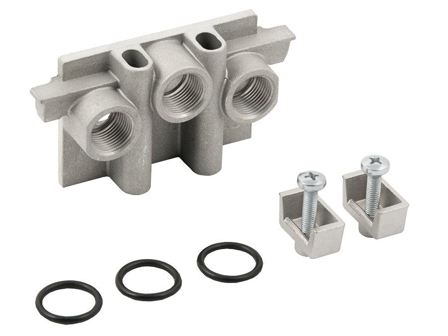
The ROSS Controls provides the end station kits required to complete manifold valve bank assemblies built with 250 Series manifold sub-bases for ISO 5599/I, ISO 5599/II, and ISO 15407 base-mounted directional control valves. An end station kit terminates both ends of the manifold stack, providing the supply air inlet connection, exhaust outlet connection, and pilot air ports that serve the entire valve bank, along with the mechanical end plates that cap the assembly and secure the interstation hardware.
Each Series end station kit contains a matched pair of end plates for the left and right ends of the manifold bank, all required screws, nuts, and seals to complete the assembly. One end station kit per manifold bank is all that is needed, regardless of the number of stations. The kit brings out the supply (port 1/P), exhaust (port 3/R and 5/EA,EB), and pilot supply (port 14) connections at a size appropriate for the combined flow demand of the valve bank.
End station kits in the series are organized by valve standard and ISO size. For ISO 5599/I (W60, W64 Series), kits are available for sizes 1, 2, and 3. For ISO 5599/II (W65 Series), kits are available for sizes 1, 2, and 3. For ISO 15407-2 (W66 Series), end stations for the plug-in manifold system are available for size 00 (18mm) and size 0 (26mm) with collective wiring terminal strip options.
As a design engineer completing a manifold valve bank design, selecting the correct end station kit is the final step in the 250-Series assembly process. The end station kit port size must be chosen to handle the maximum simultaneous flow demand of all valve stations in the bank, which requires calculating the combined Cv or flow rate of the valves when all are simultaneously in their highest-flow position.
Key Engineering Features
- Complete Manifold Termination in One Kit - Each end station kit contains both the left and right end plates, all assembly screws and nuts, and all necessary seals. One kit terminates a complete manifold bank regardless of station count, eliminating the need to source end components individually.
- Supply, Exhaust, and Pilot Port Access - The end station kit provides the physical port connections for supply air inlet to the manifold gallery, exhaust outlet from the gallery, and external pilot supply for the entire valve bank. Port sizing is scaled to the valve standard and ISO size, ensuring adequate flow capacity at the manifold ends.
- ISO 5599/I Coverage for Sizes 1, 2, and 3 - End station kits are available for ISO 5599/I manifolds in all three standard sizes, with NPT and BSPP thread options. Each kit is matched to the corresponding manifold sub-base model numbers from the 250 Series.
- ISO 5599/II Coverage for Sizes 1, 2, and 3 - Separate end station kits for ISO 5599/II (W65 Series) manifolds cover all three ISO sizes with matching NPT and BSPP thread options, compatible with the 959N91 through 964N91 manifold station assemblies.
- ISO 15407-2 Collective Wiring Options - For ISO 15407-2 (W66 Series) plug-in manifold systems, end station options include collective wiring terminal blocks that consolidate solenoid wiring from all valve stations into a single connector interface, simplifying electrical installation in multi-valve banks.
- NPT and BSPP Thread Options - All ISO 5599/I and ISO 5599/II end station kits are available in NPT and BSPP (G-thread) versions, designated by the D prefix on BSPP model numbers, for global installation compatibility.
- 54 Variants in the series - The Series includes 54 end station kit variants covering ISO 5599/I, ISO 5599/II, and ISO 15407 valve standards across all applicable ISO sizes and both NPT and BSPP thread standards.
- Hardened Seals Included - All O-ring and gasket seals included in end station kits are matched to the sealing requirements of the corresponding valve standard and manifold interface. Seals are pre-organized in the kit and do not require field sorting before assembly.
- Matched to 250 Series Manifold Sub-bases - End station kits in the series are designed specifically for use with the corresponding 250 Series manifold sub-base models. Each kit is dimensionally and functionally matched to the manifold station body it terminates.
- Supports External Pilot Supply Connection - The end station kit provides access to the external pilot supply port for the manifold bank, enabling connection of a separate pilot supply when operating at inlet pressures below the minimum pilot threshold or in vacuum service applications.
Technical Specifications
General Specifications
| Parameter | Specification |
| Compatible Manifold Standards | ISO 5599/I (W60, W64 Series, sizes 1, 2, 3); ISO 5599/II (W65 Series, sizes 1, 2, 3); ISO 15407-2 (W66 Series, sizes 00 and 0) |
| Kit Contents | Left and right end plates, assembly screws, nuts, and all required seals (O-rings and gaskets); one kit terminates one complete manifold bank |
| Port Functions Provided | Supply inlet (port 1/P), exhaust outlet (ports 3/R and 5/EA,EB), external pilot supply (port 14) where applicable |
| Thread Standards | NPT (ANSI B2.1) standard; BSPP ISO 228/1 (G) available via D prefix |
| Supply Port Size (ISO 5599/I) | 3/8" (Size 1); 1/2" (Size 2); 1" (Size 3) |
| Supply Port Size (ISO 5599/II) | 3/8" (Size 1); 1/2" (Size 2); 1" (Size 3) |
| Operating Pressure | Vacuum to 150 psig (10 bar) maximum for ISO 5599; vacuum to 145 psig (9.9 bar) for ISO 15407 |
| Flow Media | Filtered compressed air; ISO 8573-1 filtration required |
| Ambient Temperature Range | 40 to 120F (4 to 50C) |
| Media Temperature Range | 40 to 175F (4 to 80C) |
| Total Variants (Series) | 54 individual end station kit models |
Certifications & Compliance
| Certification/Standard | Detail |
| ISO 5599/I Interface Compliance | End station kits 723K86, 724K86, and 731K86 are dimensionally and functionally compliant with ISO 5599/I manifold bank termination requirements for sizes 1, 2, and 3 respectively. |
| ISO 5599/II Interface Compliance | End station kits 493N86, 494N86, and 495N86 are compliant with ISO 5599/II manifold assembly termination requirements for sizes 1, 2, and 3 respectively. |
| ISO 15407-2 Interface Compliance | ISO 15407-2 end station components RPS5620L5 and RPS5520L5 are designed to terminate W66 Series plug-in manifold assemblies in conformance with ISO 15407-2 wiring and interface requirements. |
| CE Marking (via valve assembly) | End station kits are CE-compatible accessories for use within CE-marked ROSS directional control valve manifold assemblies. CE marking applies to the complete valve manifold assembly. |
| UL, C-UL (W66 Series via valve) | When used with W66 Series ISO 15407 valves, manifold assemblies including Series end station components operate within the scope of the UL and C-UL certifications held by the W66 Series valve family. |
Typical Applications & Industries
Automotive and Assembly Automation
- ISO 5599/I size 2 manifold banks with 724K86 end station kits controlling fixture clamping and part transfer cylinders in automotive body shop tooling, where the 1/2" supply port on the end station handles the combined flow demand of 6 to 10 valve stations.
- Assembly line pneumatic tooling using ISO 5599/I size 3 manifold banks with 731K86 end station kits for high-flow valve stations controlling large bore cylinders, where the 1" end station supply port provides adequate flow capacity.
- Multi-valve pneumatic panels for robotic welding tooling using ISO 5599/II end station kits 493N86 or 494N86 to terminate manifold banks that are integrated into robot controller panels.
Packaging Machinery
- Form-fill-seal machines using ISO 5599/I size 1 manifold banks with 723K86 end station kits, where the 3/8" supply port is sized appropriately for the combined flow of 4 to 6 forming and sealing cylinder valves.
- Case packing and palletizing systems using ISO 5599/II size 2 manifold banks with 494N86 end station kits, providing a clean interface for supply and exhaust at the manifold ends in high-speed cycling applications.
- Pharmaceutical packaging machines using ISO 15407-2 collective wiring end stations (RPS5520L5) to route all solenoid wiring from the valve manifold bank to a single connector interface, simplifying installation in cleanroom-compliant enclosures.
Material Handling
- Conveyor gate and diverter valve banks using ISO 5599/I size 2 manifold banks terminated with 724K86 end station kits, where the common supply inlet handles all gate actuators from a single zone supply connection.
- Pneumatic sorting stations on distribution center conveyor systems using ISO 5599/I size 1 or 2 manifold banks where end station kits consolidate zone supply and exhaust connections at accessible piping points.
- Palletizer layer-forming cylinders controlled from ISO 5599/I size 3 manifold banks with 731K86 end station kits, providing large-bore supply and exhaust connections for high-flow layer-forming cylinder sequences.
General Industrial and OEM Equipment
- OEM machine builders specifying ISO 5599/I or ISO 5599/II manifold systems for international customers use BSPP-threaded end station kits (D723K86, D724K86, D493N86, etc.) to meet local pipe thread standards without changing the manifold sub-base selection.
- Manifold bank upgrade projects replacing older single-valve assemblies with modern ISO 5599 manifolds, where end station kits standardize supply and exhaust connection points for the new bank.
- Fieldbus-integrated valve banks using ISO 15407-2 manifold systems with collective wiring end stations, reducing installation time by consolidating multi-valve solenoid wiring into a single D-sub or terminal strip interface at the end station.
Ordering and Model Number Configuration
Select an end station kit by valve standard (ISO 5599/I, ISO 5599/II, or ISO 15407-2), ISO size, and required thread type. One kit terminates one complete manifold bank assembly. For BSPP threads, add D prefix. For ISO 15407-2 collective wiring applications, select the RPS5520L5 or RPS5620L5 based on valve size.
|
EXAMPLE - ISO 5599/I End Station Kit, Size 1, NPT:
723K86
723 = Model Code (ISO 5599/I Size 1 end station) K = Kit designation 86 = Standard configuration
EXAMPLE - ISO 5599/II End Station Kit, Size 2, BSPP:
D494N86 (D prefix = BSPP/G threads)
EXAMPLE - ISO 15407-2 Collective Wiring End Station, Size 0:
RPS5520L5 |
One end station kit is required per complete manifold bank, regardless of station count. The kit provides both left and right end plates and all assembly hardware.
For BSPP (G-thread) end station kits, add a D prefix to the NPT model number. BSPP versions are available for ISO 5599/I and ISO 5599/II kits only.
ISO 5599/I end station kit supply port sizes are: 3/8" for size 1 (723K86), 1/2" for size 2 (724K86), and 1" for size 3 (731K86). Select the kit whose supply port size is adequate for the combined flow demand of the manifold bank.
ISO 5599/II end station kit supply port sizes follow the same pattern: 3/8" for size 1 (493N86), 1/2" for size 2 (494N86), and 1" for size 3 (495N86).
For ISO 15407-2 end stations, the collective wiring models (RPS5620L5 for size 00, RPS5520L5 for size 0) include terminal strip or D-sub wiring interfaces. Contact ROSS for configuration details when integrating with specific PLC or fieldbus wiring schemes.
ISO 5599/I End Station Kits (W60, W64 Series)
| ISO Size | Supply Port Size (1,3,5) | Model Number (NPT) | Model Number (BSPP) | Contents |
| 1 | 3/8" | 723K86 | D723K86 | Left and right end plates, screws, nuts, seals |
| 2 | 1/2" | 724K86 | D724K86 | Left and right end plates, screws, nuts, seals |
| 3 | 1" | 731K86 | D731K86 | Left and right end plates, screws, nuts, seals |
ISO 5599/II End Station Kits (W65 Series)
| ISO Size | Supply Port Size | Model Number (NPT) | Model Number (BSPP) | Contents |
| 1 | 3/8" | 493N86 | D493N86 | Left and right end plates, screws, nuts, seals |
| 2 | 1/2" | 494N86 | D494N86 | Left and right end plates, screws, nuts, seals |
| 3 | 1" | 495N86 | D495N86 | Left and right end plates, screws, nuts, seals |
ISO 15407-2 End Station Options (W66 Series)
| ISO Size | Type | Model Number | Notes |
| 00 (18mm) | Collective Wiring End Station | RPS5620L5 | Includes 16-point terminal strip or D-sub connector for collective wiring of manifold solenoids |
| 0 (26mm) | Collective Wiring End Station | RPS5520L5 | Includes 16-point terminal strip or D-sub connector for collective wiring of manifold solenoids |
Accessories
250 Series Manifold Sub-bases
Manifold station bodies for ISO 5599/I, ISO 5599/II, ISO 15407-1, ISO 15407-2, ANSI, SAE, and W14 valve standards. One manifold sub-base per valve station, terminated by a Series end station kit.
Blanking Plates
Blanking plates for ISO 5599/I, ISO 5599/II, and ISO 15407 manifold stations allow unused positions in the valve bank to be sealed without installing a valve. Blanking plates install on the valve interface face of the manifold sub-base.
Interposed Pressure Regulators
Single and dual interposed pressure regulators sandwich between individual valve bodies and their manifold sub-base stations to provide independent outlet pressure control at specific stations in the manifold bank, without affecting the shared supply gallery.
Exhaust Silencers
Aluminum exhaust silencers for installation on manifold exhaust ports in the end station kit. When using a common manifold exhaust, a single silencer at the end station exhaust port serves all valve stations in the bank. Size the silencer Cv to equal or exceed the combined peak exhaust Cv of all simultaneously venting stations.
Related Products & Accessories
- 250 Series Manifold Sub-bases - Per-station manifold bodies for ISO, ANSI, SAE, and W14 valve standards that are terminated with Series end station kits. https://www.rosscontrols.com/en/series/250-manifold-sub-bases
- 249 Series Single Sub-bases - Individual sub-bases for single-valve installations where manifolding is not required. https://www.rosscontrols.com/en/series/249-single-sub-bases
- 252 Series Multi-Station Manifolds - Preassembled slim-line manifold bases for ROSS 95 Series valves in 2 through 10 station configurations. https://www.rosscontrols.com/en/series/252-multi-station-manifolds
- W60/W64 ISO 5599/I Valves - ISO 5599/I base-mounted directional control valves in sizes 1, 2, and 3 for use with 250 Series manifold sub-bases terminated with Series kits 723K86, 724K86, and 731K86. https://www.rosscontrols.com/en/series/w60-iso-5599-valves
- W65 ISO 5599/II Valves - ISO 5599/II base-mounted directional control valves for use with 250 Series manifold stations terminated with Series kits 493N86, 494N86, and 495N86. https://www.rosscontrols.com/en/series/w65-iso-5599-ii-valves
- W66 ISO 15407 Valves - ISO 15407-1 and 15407-2 base-mounted spool valves for use with RPJLP series manifold bases and RPS5520L5/RPS5620L5 end station collective wiring components. https://www.rosscontrols.com/en/series/w66-iso-15407-valves
- Valve Manifold Base Options - Interposed regulators, blanking plates, and blocking discs for ISO 15407, ISO 5599, and 95 Series valve bases. https://www.rosscontrols.com/en/categories/1305-valve-manifold-base-options
- Exhaust Silencers - Aluminum silencers rated to 290 psig for manifold exhaust ports. https://www.rosscontrols.com/en/series/90-silencers
- Electrical Connectors - DIN and M12 connectors for ROSS solenoid valves on ISO 15407 and ISO 5599 manifold sub-bases. https://www.rosscontrols.com/en/series/91-electrical-connectors
Frequently Asked Questions (FAQ)
Q: How many end station kits does a manifold bank require?
A: One end station kit per manifold bank, regardless of the number of valve stations. The kit contains both the left and right end plates, all screws, nuts, and seals needed to cap both ends of the manifold stack and provide the supply inlet, exhaust outlet, and pilot connections.
Q: Which end station kit do I use with ISO 5599/I size 2 manifold sub-bases?
A: Use end station kit 724K86 (NPT) or D724K86 (BSPP) with ISO 5599/I size 2 manifold sub-bases. This kit provides a 1/2" supply port sized for the combined flow demand of size 2 ISO 5599/I manifold banks.
Q: Can I use an ISO 5599/I end station kit with an ISO 5599/II manifold?
A: No. ISO 5599/I and ISO 5599/II end station kits are not interchangeable. The two standards have different interface geometries. Use 723K86, 724K86, or 731K86 for ISO 5599/I manifolds and 493N86, 494N86, or 495N86 for ISO 5599/II manifolds, matched to the corresponding ISO size.
Q: Does the end station kit include seals for the valve-to-base interfaces?
A: The end station kit includes seals for the end plate-to-manifold interfaces and the external port connections. Seals for the valve-to-base interface are included with the manifold sub-base station bodies from the 250 Series, not with the end station kit. Verify seal completeness for all interface types before beginning assembly.
Q: What is the supply port size on the ISO 5599/I size 3 end station kit?
A: The ISO 5599/I size 3 end station kit (731K86 and D731K86) provides a 1" supply port and 1" exhaust ports. This size is appropriate for manifold banks of ISO 5599/I size 3 valves, which have relatively high flow capacity per station and require large common gallery connection ports when multiple stations are assembled.
Q: How do I specify BSPP threads for an ISO 5599/II end station kit?
A: Add a D prefix to the model number. For example, ISO 5599/II size 1 NPT is 493N86; the BSPP version is D493N86. BSPP (G-thread, ISO 228/1 parallel) end station kit variants are available for all ISO 5599/I and ISO 5599/II sizes.
Q: What do the ISO 15407-2 collective wiring end stations (RPS5520L5, RPS5620L5) include?
A: These end stations for ISO 15407-2 W66 Series manifold assemblies include a collective wiring interface that consolidates the solenoid electrical connections from all valve stations in the manifold bank into a single multi-pin connector or terminal strip at the end station. This replaces individual per-valve wiring with a single cable run from the manifold assembly to the PLC panel, significantly reducing installation time in large manifold banks.
Q: Can an external pilot supply be connected through the end station kit?
A: Yes. The end station kit for ISO 5599/I and ISO 5599/II manifold banks provides access to the pilot supply port (port 14) for the manifold gallery. To use external pilot supply, connect the pilot source to port 14 on the end station kit and verify that the internal pilot passage plug is installed to prevent pilot air from feeding back into the supply gallery.
Q: How do I determine whether the end station supply port size is adequate for my manifold bank?
A: Calculate the combined maximum flow demand of all valve stations that may simultaneously be in their high-flow position. Sum the Cv values of those valve stations and determine the required supply port size using standard pneumatic flow equations to keep pressure drop below 10% of supply pressure at maximum flow. If the standard end station supply port is undersized, consider splitting the manifold bank into two smaller banks with separate supply connections.
Q: Are there end station kits available for ANSI or SAE manifold sub-bases?
A: Dedicated end station kits in the series are for ISO 5599/I, ISO 5599/II, and ISO 15407 manifold systems. SAE manifold sub-bases (250 Series, 580K91 through 587K91) are designed so that supply and exhaust connections are accessible at each station body and do not require separate end plate kits. ANSI manifold assemblies use a different termination approach. Consult ROSS for ANSI manifold bank termination details.
Q: What is included in the 723K86 end station kit?
A: The 723K86 ISO 5599/I size 1 end station kit contains the left end plate, right end plate, assembly screws, nuts, and all required O-ring and gasket seals. The supply and exhaust ports on the assembled end station provide 3/8" NPT connections for the manifold bank supply inlet, exhaust outlet, and pilot port. The same contents apply to the BSPP version D723K86, which has G-thread port connections.
Q: Can I order replacement seal kits for a worn or damaged end station assembly?
A: Yes. Contact ROSS Controls technical support for replacement seal kits and spare parts for Series end station assemblies. Seal replacement is recommended whenever the end station is disassembled, as seals may take a permanent set under compression. Using original ROSS seal kits ensures compatibility with the materials and dimensions of the end station and manifold interfaces.
Installation & Maintenance Guidelines
- Assemble all 250 Series manifold sub-base stations before installing the end station kit. Install the end station only after the manifold station stack is fully assembled and torqued to specification.
- Inspect all end plate sealing surfaces and O-ring grooves for damage before installing the end station kit. Replace any seals showing nicking, extrusion damage, or deformation. Using the seals included with the end station kit ensures material compatibility.
- Align the end plate with the manifold stack face before inserting screws. End plates are handed (left and right); confirm the correct orientation by checking that the supply port aligns with the supply gallery passage in the manifold station body.
- Torque end plate assembly screws evenly in a cross-pattern to the specification in the installation instructions. Uneven torque will compress the end plate seals unevenly, causing gallery leakage at the end plate interface.
- For external pilot supply, connect the pilot supply line to port 14 on the end station kit before pressurizing the manifold. Plug the internal pilot passage if it exists in the manifold design. Confirm that the pilot supply pressure equals or exceeds the inlet pressure at all times during operation.
- Connect the supply line to the supply port on the end station kit sized for the combined flow demand of the manifold bank. Do not use a supply line with inside diameter smaller than the end station supply port, as this will restrict flow and reduce available pressure across the manifold gallery.
- Install an exhaust silencer on the manifold exhaust port of the end station kit before startup if exhaust noise must be reduced. Verify that the silencer Cv equals or exceeds the combined maximum exhaust Cv of all valve stations that may vent simultaneously.
- For ISO 15407-2 collective wiring end stations, route all valve solenoid wiring from the manifold sub-base stations through the wiring raceway to the end station terminal strip or connector before installing valve bodies. Attempting to wire valve solenoids after the manifold bank is assembled makes access to terminal connections difficult.
- Before pressurizing the completed manifold assembly, apply leak detection solution to all end plate faces and verify that no bubbles form under operating pressure. Check both the left and right end plate interfaces and all port fittings on the end station kit.
- After installation and startup, allow the manifold system to cycle through several full operating sequences and recheck end plate sealing. Thermal cycling from cold ambient to operating temperature can relax seal compression slightly during initial break-in.
- Label the supply, exhaust, and pilot ports on the end station kit before routing the supply and exhaust piping. In multi-manifold panel installations, unlabeled end station ports cause frequent piping errors that are time-consuming to diagnose after the panel is assembled.
- Record the model numbers of all end station kits in the machine documentation. When seals require replacement or the manifold is disassembled for maintenance, the end station kit model number is needed to order the correct replacement seal kit from ROSS.
Warranty & Global Support
ROSS Controls provides a one-year warranty on all products, covering defects in material and workmanship from the date of purchase.
Global technical support is available through ROSS offices in the USA (headquarters in Ferndale, Michigan), Canada, Brazil, Germany, France, United Kingdom, India, China, and Japan.
For end station kit selection guidance, compatibility confirmation, and replacement seal kit ordering, contact ROSS Controls at +1-248-764-1800 or visit rosscontrols.com.
For complete technical data, dimensional drawings, and manifold assembly instructions, visit the ROSS Controls product page or contact ROSS Controls at (800) 438-7677.
Download Documents
End Station Kits
