Single Sub-bases ISO, ANSI, SAE, and W14 Valves
- ISO 15407-1
- ISO 5599-1
- SAE
- ANSI
- W14
loading...
loading...
Product Overview
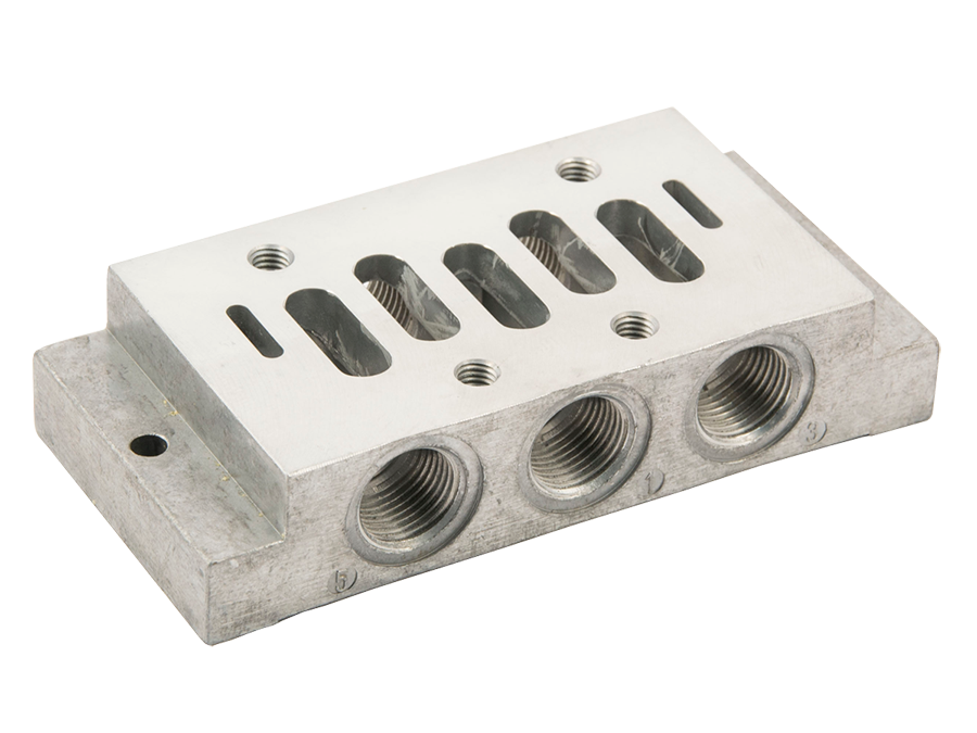
The ROSS Controls is the comprehensive range of single sub-bases designed to interface ROSS base-mounted directional control valves to pneumatic circuit piping in individual, non-manifolded installations. These sub-bases establish the mechanical mounting interface, internal port passages, and threaded connections that allow valves to be bolted in place and pneumatically connected without separate inline plumbing at each valve port.
Single sub-bases in the series are offered across all major valve interface standards supported by ROSS: ISO 15407-1 and 15407-2 (drop-cord and plug-in W66 Series sizes 00 and 0), ISO 5599/I (W60 and W64 Series, sizes 1, 2, and 3), ISO 5599/II (W65 Series, sizes 1, 2, and 3), ANSI W70 and W74 Series (sizes 1, 2.5, 4, 10, and 20), SAE 80 and 84 Series (sizes 125, 250, and 500), and the W14 miniature valve series. Both side-ported and bottom-ported configurations are available depending on the valve type and installation geometry.
As a design engineer specifying base-mounted pneumatic valve systems, selecting the correct sub-base is as important as selecting the valve itself. The sub-base determines port location, thread type, and whether remote pilot supply connections are accessible. The Series is designed to mate precisely with corresponding ROSS valve bodies, ensuring that all internal passages align, all O-ring face seals compress correctly, and all valve functions operate as intended without field modification.
ROSS single sub-bases are machined components made from cast or bar stock aluminum, supplied with all necessary mounting hardware and interface seals. They are compatible with interposed flow controls and pressure regulators where these options are available for the corresponding valve standard. Indicator light options are available for ANSI size 1 and 2.5 sub-bases to provide visual energization feedback at each valve station.
Key Engineering Features
- Universal Standard Coverage - A single product family covers all major pneumatic valve interface standards: ISO 15407-1, ISO 15407-2, ISO 5599/I, ISO 5599/II, ANSI W70/W74, SAE 80/84, and W14 miniature valves, simplifying procurement and maintenance across a multi-standard facility.
- Side-Ported and Bottom-Ported Options - Side-ported sub-bases route all process and pilot connections to the sides of the base for panel-mounted or rail-mounted installations. Bottom-ported variants route supply, work, and exhaust connections to the underside of the base for through-panel piping or manifold block integration.
- NPT and BSPP Thread Options - Standard sub-bases use NPT (ANSI B2.1) threads. BSPP (ISO 228/1 parallel) thread variants are available by adding a D prefix to the model number, supporting global installation requirements without switching to a different sub-base family.
- Integrated O-Ring Face Seal Interface - All ROSS sub-bases use O-ring face seals at the valve-to-base interface. This configuration requires no thread sealant on interface connections and provides leak-free sealing regardless of torque variation at assembly, which is critical for reliable long-term pneumatic system performance.
- External and Remote Pilot Supply Access - Sub-bases for ISO 5599/I and ISO 15407 valves provide threaded pilot ports for external pilot supply connection, enabling operation below the minimum internal pilot threshold or for vacuum service where external pilot is required.
- Optional Indicator Lights - ANSI size 1 and 2.5 sub-bases are available with one or two indicator lights for visual confirmation of solenoid energization. These are particularly useful during commissioning and troubleshooting in multi-valve systems.
- Interposed Accessory Compatibility - For applicable valve standards, single sub-bases are compatible with interposed flow controls and dual-pressure regulators that sandwich between the valve and base, allowing independent outlet pressure or speed control at each valve station without additional piping.
- 143 Variants in the series - The Series encompasses 143 individual sub-base variants, providing precise coverage of all valve types, port sizes, porting orientations, thread standards, and indicator light configurations in a single orderable series.
- Included Mounting Hardware and Seals - ROSS single sub-bases ship with all required O-rings and mounting fasteners to complete the valve-to-base assembly, eliminating the need to source additional hardware and reducing installation time at the machine.
- Precision-Machined Aluminum Construction - Sub-base bodies are machined from aluminum, providing structural rigidity, corrosion resistance in typical industrial atmospheres, and light weight. The machined port passages maintain tight dimensional tolerances to ensure valve alignment and seal compression within specification.
Technical Specifications
General Specifications
| Parameter | Specification |
| Compatible Valve Standards | ISO 15407-1 (W66 Size 00, 0); ISO 15407-2 (W66 Size 00, 0); ISO 5599/I (W60, W64 Sizes 1, 2, 3); ISO 5599/II (W65 Sizes 1, 2, 3); ANSI W70/W74 (Sizes 1, 2.5, 4, 10, 20); SAE 80/84 (Sizes 125, 250, 500); W14 Miniature Series |
| Porting Configurations | Side-ported; Bottom-ported (select sizes/standards) |
| Thread Standards | NPT (ANSI B2.1) standard; BSPP ISO 228/1 (G) available via D prefix |
| Port Size Range | 1/8" through 1-1/2" depending on valve standard and size |
| Operating Pressure | Vacuum to 150 psig (10 bar) maximum; ISO 15407 valves rated vacuum to 145 psig (9.9 bar) |
| Flow Media | Filtered compressed air; ISO 8573-1 filtration required |
| Ambient Temperature Range | 40 to 120F (4 to 50C) for ISO and ANSI/SAE; 5 to 120F (-15 to 50C) for W14 Series |
| Media Temperature Range | 40 to 175F (4 to 80C) for ISO and ANSI/SAE; 5 to 175F (-15 to 80C) for W14 Series |
| Body Material | Cast aluminum; bar stock aluminum (W14 and select ISO series) |
| Interface Sealing | O-ring face seals at valve-to-base interface; included with sub-base |
| Indicator Light Options | One or two indicator lights available for ANSI Size 1 and 2.5 sub-bases |
| Total Variants (Series) | 143 individual sub-base models |
Certifications & Compliance
| Certification/Standard | Detail |
| CE Marking | Sub-bases are CE-marked as compatible accessories for CE-certified ROSS directional control valves. Compatibility confirmed for ISO, ANSI, SAE, and W14 valve families. |
| ISO 15407-1 Interface | Sub-bases for W66 Series comply with ISO 15407-1 drop-cord valve-to-base interface dimensions for sizes 00 (18mm) and 0 (26mm). |
| ISO 15407-2 Interface | Sub-bases for W66 Series comply with ISO 15407-2 plug-in valve-to-base interface dimensions for sizes 00 (18mm) and 0 (26mm). |
| ISO 5599/I Interface | Sub-bases for W60 and W64 Series comply with ISO 5599/I valve-to-base mounting interface for sizes 1, 2, and 3. |
| ISO 5599/II Interface | Sub-bases for W65 Series comply with ISO 5599/II valve-to-base mounting interface for sizes 1, 2, and 3. |
| ANSI B93.55M Electrical Interface | ANSI sub-bases with solenoid pilot valves are available with electrical connections conforming to ANSI B93.55M standard, in addition to the standard DIN connection. |
| UL, C-UL, CE (via valve) | Sub-bases used with W66 Series ISO 15407 valves operate within systems that carry UL, C-UL, and CE certification on the valve assembly. Sub-base selection must correspond to the certified valve interface. |
Typical Applications & Industries
Automotive and Machine Tool Assembly
- Individual valve-and-sub-base assemblies for controlling pneumatic cylinders at each actuator station in body shop tooling, fixture clamping, and part transfer applications where manifolding is not practical.
- Machine tool pneumatic circuits where each actuator has its own dedicated valve and sub-base for independent pressure adjustment using interposed regulators.
- Automotive paint line actuators where bottom-ported sub-bases allow piping to route through machine frames without exposed surface fittings.
Food and Beverage Processing
- Hygienic machine installations where individual sub-bases allow each valve to be replaced independently during scheduled maintenance without disturbing adjacent valve piping.
- Conveying, diverting, and gating actuators in food processing lines using ISO 5599/I or ISO 5599/II base-mounted valves with side-ported sub-bases for simple hose connection.
- Filling, capping, and labeling machines where ANSI size 1 or 2.5 sub-bases with indicator lights simplify troubleshooting during production.
Packaging and Material Handling
- Case erecting, carton sealing, and palletizing systems using SAE size 125 or 250 valves on single sub-bases where high-flow individual actuators require dedicated valve stations.
- Pick-and-place systems using W14 miniature valves on 516B91 single sub-bases for compact installations in space-constrained machine assemblies.
- Pneumatic conveying diverters using ANSI size 4 or 10 valves on large-port sub-bases with 3/4" or 1" outlet connections for high-flow applications.
General Industrial and OEM Equipment
- OEM machine builders using ISO 5599/II sub-bases to meet international valve interface standardization requirements while sourcing ROSS valve bodies that match customer specifications.
- Replacement and retrofit installations where existing sub-bases must be replaced with compatible models using the same port size and thread standard, making model number traceability critical.
- Pilot supply isolation in complex circuits where sub-base pilot port access allows external pilot supply connection at individual valve stations without modifying valve body plumbing.
Ordering and Model Number Configuration
Single sub-bases in the series are ordered by selecting the model number that corresponds to the valve standard, ISO or ANSI size, port size, porting orientation (side or bottom), and thread type. For BSPP (G) threads, add a D prefix to the NPT model number. Indicator light options apply to ANSI size 1 and 2.5 only.
|
EXAMPLE - ISO 5599/I Side-Ported Sub-base, ISO Size 2, 3/8" NPT Threads:
2079C01
2079 = Model Code (ISO 5599/I Size 2, side-ported) C = Revision/Configuration Code 01 = Standard Configuration
EXAMPLE - ANSI Size 2.5, 1/2" outlet, Solenoid Pilot, One Indicator Light:
483K91
EXAMPLE - BSPP Thread Variant (D Prefix):
D2079C01 (D prefix = BSPP/G threads) |
For BSPP (G-thread, ISO 228/1 parallel) models, add a D prefix to the NPT model number. Not all sizes and porting configurations are available in BSPP.
For ANSI size 1 and 2.5 sub-bases with solenoid pilot valves, indicator light options are available: models with 525K91/527K91 include one light; models with 526K91/528K91 include two lights.
ISO 15407-1 sub-bases RPL02-01-80 (size 00) and RPL01-02-80 (size 0) support external, single, and double remote pilot supply. ISO 15407-2 sub-bases in the PS5511 and PS5611 families have enclosure/lead length options coded in the suffix.
ANSI sub-bases apply equally to solenoid pilot and pressure-controlled W70/W74 valve models. Verify valve actuation type when selecting sub-base for pressure-controlled applications.
SAE sub-bases list port size pairs in the format A,B (work ports) / P,EA,EB (supply and exhaust ports). Confirm both supply and work port sizes when ordering.
ISO 5599/I Sub-bases (W60, W64 Series) - Side-Ported
| ISO Size | Port Size (2,4 / 1,3,5 / 12,14) | Model Number (NPT) | Model Number (BSPP) |
| 1 | 1/4 / 1/4 / 1/8 | 2077C01 | D2077C01 |
| 2 | 3/8 / 3/8 / 1/8 | 2079C01 | D2079C01 |
| 3 | 1/2 / 1/2 / 1/8 | 2081C01 | D2081C01 |
ISO 5599/I Sub-bases (W60, W64 Series) - Bottom-Ported
| ISO Size | Port Size (2,4 / 1,3,5 / 12,14) | Model Number (NPT) |
| 1 | 1/8 / 1/4 / 1/8 | 654K91 |
| 2 | 3/8 / 3/8 / 1/8 | 642K91 |
| 2 | 1/2 / 1/2 / 1/8 | 643K91 |
| 3 | 3/4 / 3/4 / 1/2 | 644K91 |
ISO 5599/II Sub-bases (W65 Series) - Side and Bottom-Ported
| ISO Size | Port Size | Model Number (NPT) | Model Number (BSPP) |
| 1 | 1/4 Side | 949N91 | D949N91 |
| 1 | 1/4 Side/Bottom | 971N91 | |
| 1 | 3/8 Side | 950N91 | D950N91 |
| 1 | 3/8 Side/Bottom | 972N91 | |
| 2 | 3/8 Side | 951N91 | |
| 2 | 3/8 Side/Bottom | 952N91 | |
| 2 | 1/2 Side | 953N91 | D953N91 |
| 2 | 1/2 Side/Bottom | 954N91 | |
| 3 | 1/2 Side | 955N91 | D955N91 |
| 3 | 1/2 Side/Bottom | 956N91 | D956N91 |
| 3 | 3/4 Side | 957N91 | D957N91 |
| 3 | 3/4 Side/Bottom | 958N91 | D958N91 |
ISO 15407-1 Sub-bases (W66 Series) - Side-Ported
| ISO Size | Port Size | Model Number (NPT) | Model Number (BSPP) | Notes |
| 00 (18mm) | 1/8 | RPL02-01-80 | RPL02-01-70 | External, single, or double remote pilot capable |
| 0 (26mm) | 1/4 | RPL01-02-80 | RPL01-02-70 | External, single, or double remote pilot capable |
ANSI Sub-bases (W70, W74 Series) - Side-Ported, Solenoid Pilot
| ANSI Size | Outlet Port | Model (No Light) | Model (One Light) | Model (Two Lights) | Avg Cv |
| 1 | 1/4" | 500B91 | 525K91 | 526K91 | 0.9-1.0 |
| 1 | 3/8" | 501B91 | 527K91 | 528K91 | 0.9-1.0 |
| 2.5 | 3/8" | 474K91 | 482K91 | 484K91 | 2.0-2.5 |
| 2.5 | 1/2" | 475K91 | 483K91 | 485K91 | 2.0-2.5 |
| 4 | 3/8" | 361B91 | 4.2 | ||
| 4 | 1/2" | 362B91 | 4.2 | ||
| 4 | 3/4" | 363B91 | 4.2 | ||
| 10 | 3/4" | 364B91 | 10-11 | ||
| 10 | 1" | 365B91 | 10-11 | ||
| 10 | 1-1/4" | 366B91 | 10-11 | ||
| 20 | 1-1/4" | 367B91 | 22 | ||
| 20 | 1-1/2" | 368B91 | 22 |
SAE Sub-bases (Series 80, 84) - Side-Ported
| SAE Size | Port Size (A,B / P,EA,EB) | Model Number (NPT) |
| 125 | 1/4 / 3/8 | 577K91 |
| 125 | 3/8 / 3/8 | 578K91 |
| 125 | 3/8 / 3/8 | 579K91 |
| 250 | 1/4 / 3/8 | 539K91 |
| 250 | 3/8 / 1/2 | 540K91 |
| 250 | 1/2 / 1/2 | 541K91 |
| 250 | 3/4 / 3/4 | 542K91 |
| 500 | 1/2 / 3/4 | 582K91 |
| 500 | 3/4 / 3/4 | 728K91 |
| 500 | 3/4 / 1 | 583K91 |
| 500 | 1 / 1 | 584K91 |
W14 Miniature Series Single Sub-base
| Port Threads | Model Number | Notes |
| 1/8 NPT | 516B91 | For individual W14 valve installation; includes valve-to-base O-rings and mounting screws |
Accessories
Interposed Flow Controls
Bidirectional and one-way flow controls are available as interposed accessories that sandwich between the valve and sub-base, providing independent speed control of each actuator at the valve station without separate meter-in or meter-out plumbing. Available for ISO 5599/I, ISO 5599/II, and select ANSI valve families.
Interposed Pressure Regulators
Single and dual interposed pressure regulators are available for ISO 15407-2 (W66 size 0 and size 00), ISO 5599/I, and SAE size 125 and 250 valves. A dual regulator allows independent pressure settings for each work port output, controlled at the valve station. The regulator sandwiches between the valve and sub-base.
Exhaust Silencers
Aluminum exhaust silencers rated to 290 psig (20 bar) are available in male thread configurations for all exhaust port sizes from 1/8" to 1/2". Silencer flow capacity must equal or exceed valve exhaust flow capacity. Model examples: 5500A1003 (1/8" NPT, Cv 1.2), 5500A2003 (1/4" NPT, Cv 2.1), 5500A3013 (3/8" NPT, Cv 2.7), 5500A4003 (1/2" NPT, Cv 2.7).
Electrical Connectors
ROSS offers EN 175301-803 (DIN 43650) connectors in Form A, Form B, and MICRO-MINI configurations compatible with solenoid valves on ISO 15407-2 and ISO 5599 sub-bases. Lighted connectors are available for 24 VDC and 110/120 VAC. Contact ROSS for prewired connector assemblies.
Related Products & Accessories
- 250 Series Manifold Sub-bases - Multi-station manifold bases for ISO, ANSI, SAE, and W14 valves, sharing common supply and exhaust connections across multiple valve stations. https://www.rosscontrols.com/en/series/250-manifold-sub-bases
- 251 Series End Station Kits - End plates, screws, nuts, and seals required to terminate assembled manifold sub-base stacks for ISO 5599/I, ISO 5599/II, and ISO 15407 valve manifolds. https://www.rosscontrols.com/en/series/251-end-station-kits
- 252 Series Multi-Station Manifolds - Preassembled slim-line manifold bases for ROSS 95 Series valves in 2, 4, 6, 8, and 10 station configurations. https://www.rosscontrols.com/en/series/252-multi-station-manifolds
- W66 Series ISO 15407 Valves - ISO 15407-1 and 15407-2 base-mounted spool valves in size 00 (18mm) and size 0 (26mm) for use with RPL and PS5511/PS5611 sub-bases. https://www.rosscontrols.com/en/series/w66-iso-15407-valves
- W60/W64 Series ISO 5599/I Valves - ISO 5599/I base-mounted directional control valves in sizes 1, 2, and 3 for use with Series side-ported and bottom-ported sub-bases. https://www.rosscontrols.com/en/series/w60-iso-5599-valves
- W65 Series ISO 5599/II Valves - ISO 5599/II base-mounted valves in sizes 1, 2, and 3 for use with 949N91 through 958N91 Series sub-bases. https://www.rosscontrols.com/en/series/w65-iso-5599-ii-valves
- W70/W74 ANSI Series Valves - ANSI-standard base-mounted directional control valves in sizes 1 through 20 for use with 500B91 through 368B91 single sub-bases. https://www.rosscontrols.com/en/series/w70-ansi-valves
- W14 Miniature Series Valves - Compact 3/2 base-mounted valves for use with the 516B91 single sub-base in space-constrained installations. https://www.rosscontrols.com/en/series/w14-miniature-valves
- Valve Manifold Base Options - Interposed regulators, blanking plates, and blocking discs for ISO 15407, ISO 5599, and 95 Series valve bases. https://www.rosscontrols.com/en/categories/1305-valve-manifold-base-options
- Exhaust Silencers - Aluminum silencers rated to 290 psig for exhaust port sizes 1/8" through 1/2", compatible with all ROSS base-mounted valve exhaust ports. https://www.rosscontrols.com/en/series/90-silencers
Frequently Asked Questions (FAQ)
Q: What is the difference between a side-ported and a bottom-ported sub-base?
A: A side-ported sub-base brings all process connections (supply, work ports, exhaust, and pilot ports) out the sides of the base body. A bottom-ported sub-base routes supply, work, and exhaust connections through the bottom face of the base, allowing piping to pass through machine panels or nest into manifold block interfaces. Bottom-ported variants are typically used when surface fittings would create interference with adjacent hardware or when panel-through piping is required.
Q: Can I use an ISO 5599/I sub-base with an ISO 5599/II valve?
A: No. ISO 5599/I (W60, W64 Series) and ISO 5599/II (W65 Series) have different valve-to-base interface geometries and are not interchangeable. The ISO designation and internal port layout differ between the two standards. You must select a sub-base that matches the specific ISO standard of the valve being installed.
Q: How do I specify BSPP threads instead of NPT?
A: Add a D prefix to the NPT model number. For example, ISO 5599/I size 2 side-ported NPT is 2079C01; the BSPP version is D2079C01. Not every sub-base size or porting configuration has a BSPP variant. Confirm availability by checking the ROSS catalog or contacting ROSS Controls.
Q: What is the maximum operating pressure for Series sub-bases?
A: The maximum operating pressure is 150 psig (10 bar) for ISO 5599/I, ISO 5599/II, ANSI, SAE, and W14 sub-bases. ISO 15407 sub-bases are rated to a maximum of 145 psig (9.9 bar). These limits apply to the sub-base body and conform to the pressure ratings of the valve interfaces they support.
Q: Do I need to order mounting screws separately?
A: No. ROSS single sub-bases include all necessary O-rings and mounting fasteners to complete the valve-to-base assembly. Verify that the sub-base kit contents match the fastener pattern for the valve model being installed. For some ISO 15407 manifold assemblies, gaskets and hardware are included with the manifold rather than the individual base.
Q: Which sub-base models include indicator lights?
A: Indicator light options are available for ANSI size 1 and size 2.5 solenoid pilot sub-bases only. Model 525K91 and 527K91 (size 1, 1/4" and 3/8" outlet) include one indicator light. Models 526K91 and 528K91 include two lights for double-solenoid valve applications. Models 482K91, 483K91, 484K91, and 485K91 provide indicator light options for size 2.5.
Q: Can I use a single sub-base with a pressure-controlled (pneumatic pilot) valve?
A: Yes, for applicable valve families. ANSI W70/W74 and ISO 5599/I valves have pressure-controlled configurations that mount on the same sub-bases as solenoid versions. For ISO 15407 sub-bases, check the ROSS catalog note: the size 00 sub-base RPL02-01-80 cannot be used with pressure-controlled valves. The size 0 sub-base RPL01-02-80 is compatible with pressure-controlled valves.
Q: Is an external pilot supply port available on the sub-base?
A: Yes, for ISO 5599/I and ISO 15407 sub-bases. The pilot port (port 14 for ISO 5599/I) is accessible on the sub-base for connecting an external pilot supply when inlet pressure is below the required pilot pressure or when the valve is used in vacuum service. The unused internal pilot connection must be plugged when external pilot supply is connected.
Q: Can interposed flow controls or regulators be added to a single sub-base?
A: Yes, for applicable valve standards. Interposed flow controls and single or dual pressure regulators are available as sandwich modules that install between the valve and sub-base body. These are available for ISO 15407-2 size 0, ISO 5599/I sizes 1 through 3, and SAE sizes 125 and 250. Contact ROSS for part numbers and compatibility with specific sub-base models.
Q: What filtration level is required for the air supply to the sub-base?
A: Supply air must be filtered per ISO 8573-1 requirements. A 5-micron particle filter is recommended as the minimum to prevent contamination from entering valve passages and causing premature wear or sticking. For valves used in non-lubricated service, ensure the air supply is also oil-free at the filtration level the valve seal material requires.
Q: Can W14 valves be manifolded using single sub-bases?
A: No. Single sub-base 516B91 is for individual W14 valve installation only. For manifolded W14 installations, the 535K91 manifold base component from the 250 Series is required. Manifolded installations allow multiple W14 valves to share a common supply and exhaust connection through a single manifold body.
Q: Are Series sub-bases compatible with serial bus communication systems?
A: Single sub-bases for ISO 15407-2 (W66 Series) valves are compatible with serial bus gateway systems when the appropriate enclosure/lead length option code is selected in the model number. Serial bus configurations require manifold bases (250 Series) rather than single sub-bases. Contact ROSS for serial bus system design and sub-base selection in networked valve applications.
Installation & Maintenance Guidelines
- Before installation, verify that the sub-base model number matches the valve series, ISO or ANSI size, and port size required. Installing a mismatched sub-base will result in misaligned internal passages and potential seal bypass leakage.
- Inspect all O-ring face seals on the valve-to-base interface before assembly. Replace any seals that are nicked, deformed, or missing. O-rings must be seated correctly in their grooves; do not stretch or pinch seals during assembly.
- Mount the sub-base to the machine structure before installing the valve on the base. This sequence allows the sub-base to be torqued to the panel without applying side loads to the valve body.
- Apply consistent torque to all valve-to-base mounting screws using a calibrated torque wrench. Uneven torque will tilt the valve interface and can cause seal leakage at the higher-pressure work ports. Follow torque specifications in the valve installation instructions.
- For side-ported sub-bases, verify that all pipe connections are made to the correct port designations before commissioning. Port 1 is supply, ports 2 and 4 are work outputs, ports 3 and 5 are exhaust, and ports 12 and 14 are pilot supply (ISO 5599/I convention). Mislabeled connections can cause machine motion in the wrong direction.
- For bottom-ported sub-bases, route supply and work port tubing through the machine panel before bolting the sub-base in place. Attempting to make bottom-port connections after the base is fully mounted often results in poor access and inadequate torque on fittings.
- When using external pilot supply, connect the pilot supply to port 14 on ISO 5599/I sub-bases and verify that the internal pilot connection is plugged. External pilot pressure must equal or exceed inlet pressure. Failure to plug the internal pilot passage will result in pilot air escaping from the sub-base and erratic valve operation.
- Supply filtered air at all times. Connect the supply only after confirming the filter regulator in the supply line is set to the required pressure and is functioning correctly. Operating below the minimum pilot pressure of 15 psig (ISO 5599, size 1) or 30 psig (ANSI) will result in incomplete valve shifting.
- When installing indicator light versions of ANSI sub-bases, connect the indicator light leads to the appropriate control voltage. Indicator lights on 525K91 and 526K91 bases are powered from the solenoid circuit; verify voltage compatibility before wiring.
- For SAE sub-base installations, note that port size pairs list the work ports (A, B) separately from the supply and exhaust ports (P, EA, EB). Route appropriately sized supply and return lines to each port pair to avoid pressure drop from undersized supply connections.
- Verify that exhaust silencers installed on sub-base exhaust ports have a Cv rating equal to or greater than the exhaust Cv of the valve. A silencer with insufficient flow capacity will create back pressure on the exhaust side, slowing actuator return speeds and increasing cycle time.
- After installation, perform a functional test with the machine de-energized by actuating the manual override button on the valve body. Confirm that each actuator moves in the correct direction before energizing the solenoid circuit. This step identifies mis-piped port connections before machine operation begins.
Warranty & Global Support
ROSS Controls provides a one-year warranty on all products, covering defects in material and workmanship from the date of purchase.
Global technical support is available through ROSS offices in the USA (headquarters in Ferndale, Michigan), Canada, Brazil, Germany, France, United Kingdom, India, China, and Japan.
For sub-base selection assistance, dimensional data, and compatibility confirmation, contact ROSS Controls at +1-248-764-1800 or visit rosscontrols.com.
For complete technical data, dimensional drawings, and CAD models, visit the ROSS Controls product page or contact ROSS Controls at (800) 438-7677.
Download Documents
Single Sub-bases
