Manifold Sub-bases ISO, ANSI, SAE, and W14 Valves
- ISO 15407-1 & -2
- ISO 5599-1 & -2
- ANSI
- SAE
- W14
loading...
loading...
Product Overview
The ROSS Controls is the comprehensive family of manifold sub-bases for assembling multi-station pneumatic valve banks across all major base-mounted valve interface standards. Unlike single sub-bases that provide independent piping connections at each valve, manifold sub-bases link individual valve stations through shared internal supply and exhaust galleries, reducing the number of pipe connections required and consolidating valve installations into compact, integrated assemblies.
The Series covers all ROSS base-mounted valve families: ISO 15407-1 and 15407-2 (W66 Series, sizes 00 and 0), ISO 5599/I (W60 and W64 Series, sizes 1, 2, and 3), ISO 5599/II (W65 Series, sizes 1, 2, and 3), ANSI W70 and W74 Series (sizes 1, 2.5, 4, and 10), SAE 80 and 84 Series (sizes 125, and 500), and the W14 miniature series with the 535K91 manifold component. The series includes 238 variants, covering side-ported and bottom-ported configurations with NPT and BSPP thread options.
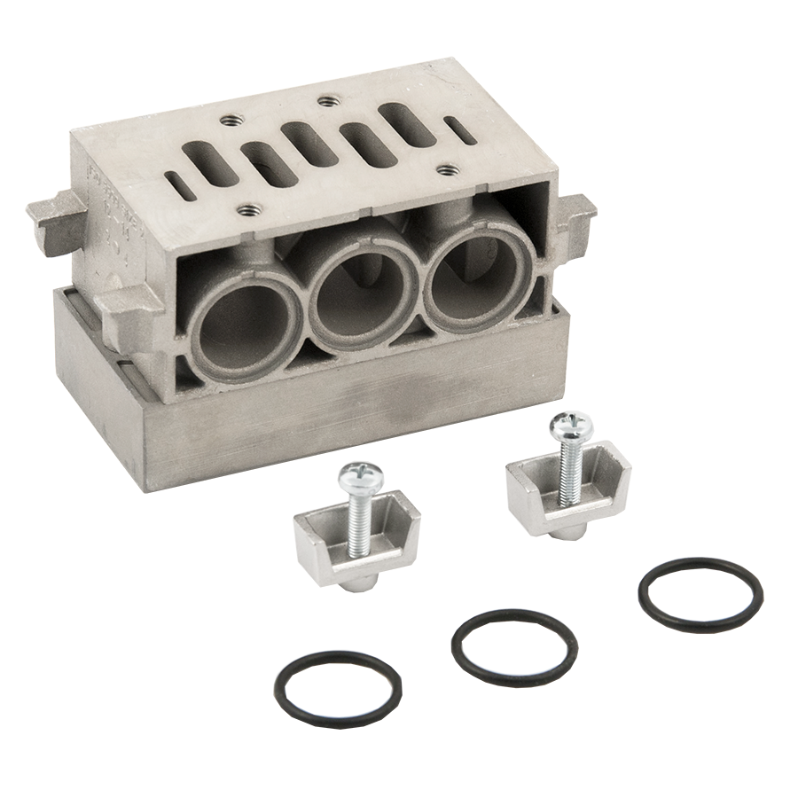
Manifold sub-bases are per-station components. Each valve station in a manifold assembly uses one manifold sub-base body. An end station kit from the 251 Series terminates the manifold stack, providing the supply inlet, exhaust outlet, and any pilot connections at the ends of the assembled bank. Multiple manifold stations bolt together with inter-station O-ring face seals creating the internal supply and exhaust galleries that run the length of the bank.
For design engineers planning multi-actuator pneumatic systems, the series manifold approach reduces pipe fitting count, simplifies panel layout, enables valve replacement without disturbing other stations, and facilitates serial bus communication wiring in ISO 15407-2 and ISO 5599/II applications. The Series sub-bases are sized and drilled to accept the same interposed flow control and pressure regulator accessories available with 249 Series single sub-bases.
Key Engineering Features
- Shared Supply and Exhaust Galleries - Manifold sub-bases interlock to create continuous internal passages for supply air and exhaust air running the length of the valve bank, eliminating individual supply and exhaust fittings at each station and dramatically reducing the pipe connection count in multi-valve installations.
- Per-Station Modular Assembly - Each manifold station is an individual machined body that bolts to adjacent stations with O-ring face seals at the inter-station interfaces. This construction allows valve banks to be assembled in any number of stations, valves to be replaced or relocated without disturbing adjacent stations, and stations to be added to an existing bank without rebuilding the assembly.
- 238 Variants Across All Valve Standards - The Series covers ISO 15407-1, ISO 15407-2, ISO 5599/I, ISO 5599/II, ANSI W70/W74, SAE 80/84, and W14 manifold components in a single series, providing a consistent procurement and documentation framework for facilities operating multiple valve standards.
- Side-Ported and Bottom-Ported Options - Side-ported manifold sub-bases provide supply, work port, exhaust, and pilot connections at the sides of each station body. Bottom-ported variants route work port and pilot connections to the underside, allowing piping to exit below the valve bank for cleaner panel installations or through-panel connection.
- NPT and BSPP Thread Availability - Standard manifold sub-bases use NPT threads. BSPP (G-thread, ISO 228/1 parallel) versions are available via D prefix ordering on all applicable models, supporting global installation requirements without a separate product family.
- ISO 5599/I Front-Ported and Bottom-Ported Manifold Options - ISO 5599/I manifold sub-bases are available in side-ported and bottom-ported configurations to accommodate work port routing requirements in horizontal and vertical valve bank orientations.
- Interposed Accessory Compatibility - Manifold sub-bases accept the same interposed flow control and pressure regulator modules as single sub-bases for compatible valve standards, enabling independent speed or pressure adjustment at individual stations within a manifold bank.
- Serial Bus Communication Compatibility - ISO 15407-2 and ISO 5599/II manifold sub-bases are engineered to support ROSS serial bus communication systems, including ControlNet, DeviceNet, EtherNet/IP, Profibus, and CANopen gateways. Enclosure and lead length option codes in the model number define bus compatibility.
- Matching Interstation O-Ring Sealing - Inter-station faces on all Series manifold sub-bases use O-ring face seals to create leak-free supply and exhaust gallery joints. All seals are included with each manifold station, and no thread sealant is required at internal interfaces.
- Compatible with End Station Kits (251 Series) - Each manifold bank assembled with Series sub-bases requires a 251 Series end station kit to cap the manifold ends and provide supply inlet, exhaust outlet, and pilot ports. End station kits are matched by valve standard and ISO size to the manifold sub-bases used.
Technical Specifications
General Specifications
| Parameter | Specification |
| Compatible Valve Standards | ISO 15407-1 (W66 Size 00, 0); ISO 15407-2 (W66 Size 00, 0); ISO 5599/I (W60, W64 Sizes 1, 2, 3); ISO 5599/II (W65 Sizes 1, 2, 3); ANSI W70/W74 (Sizes 1, 2.5, 4, 10); SAE 80/84 (Sizes 125, 500); W14 Miniature Series |
| Assembly Method | Per-station manifold bodies bolted together with O-ring face seals at inter-station interfaces; terminated by 251 Series end station kits |
| Porting Configurations | Side-ported (front-ported); Bottom-ported; select models available with both side and bottom connections |
| Thread Standards | NPT (ANSI B2.1) standard; BSPP ISO 228/1 (G) available via D prefix |
| Port Size Range | 1/8" through 1" at supply/exhaust ends; work port sizes 1/8" through 3/4" depending on valve standard and ISO size |
| Operating Pressure | Vacuum to 150 psig (10 bar) maximum; ISO 15407 rated to 145 psig (9.9 bar) |
| Flow Media | Filtered compressed air; ISO 8573-1 filtration required |
| Ambient Temperature Range | 40 to 120F (4 to 50C) for ISO and ANSI/SAE; 5 to 120F (-15 to 50C) for W14 Series |
| Media Temperature Range | 40 to 175F (4 to 80C) for ISO and ANSI/SAE; 5 to 175F (-15 to 80C) for W14 Series |
| Body Material | Cast aluminum; machined aluminum |
| Hardware Included | Gaskets and assembly hardware included with each manifold station for inter-station assembly |
| Total Variants (Series) | 238 individual manifold station models |
Certifications & Compliance
| Certification/Standard | Detail |
| ISO 15407-1 Interface Compliance | Manifold bases for W66 Series comply with ISO 15407-1 drop-cord valve-to-base mounting interface for sizes 00 (18mm) and 0 (26mm), ensuring interchangeability with other ISO 15407-1 compliant components. |
| ISO 15407-2 Interface Compliance | Manifold bases for W66 Series comply with ISO 15407-2 plug-in valve-to-base mounting interface, including serial bus communication compatibility in applicable configurations. |
| ISO 5599/I Interface Compliance | Manifold sub-bases for W60 and W64 Series comply with ISO 5599/I valve-to-base interface for sizes 1, 2, and 3. |
| ISO 5599/II Interface Compliance | Manifold station assemblies for W65 Series comply with ISO 5599/II valve-to-base interface for sizes 1, 2, and 3. |
| CE Marking (via valve assembly) | Series manifold sub-bases are CE-compatible accessories used within CE-marked ROSS directional control valve assemblies. CE marking applies to the valve assembly as a whole. |
| Serial Bus Communication Compatibility | ISO 15407-2 and ISO 5599/II manifold stations are engineered for compatibility with ROSS serial bus gateway systems supporting ControlNet, DeviceNet, EtherNet/IP, Profibus, and CANopen fieldbus protocols. |
| ANSI B93.55M Electrical Interface (ANSI Manifolds) | ANSI W70/W74 manifold sub-bases with solenoid pilot valves are available with electrical connections conforming to ANSI B93.55M for plug-in solenoid connections. |
Typical Applications & Industries
Automotive Assembly and Body Shop
- Multi-valve manifold banks controlling fixture clamping, part transfer, and welding gun cylinders in automotive body shop tooling, where a single supply connection feeds all valve stations and individual work ports route to each actuator.
- Assembly line pneumatic tooling using ANSI size 4 or 10 manifold sub-bases to control high-flow cylinders from a compact, shared-supply manifold bank, reducing panel space and connection count.
- Paint line automation where ISO 5599/II manifold sub-bases provide serial bus communication capability for integration with DeviceNet or Profibus controllers.
Packaging Machinery
- Case erecting, fill, seal, and palletizing stations using SAE size 125 or manifold sub-bases to control forming and clamping cylinders from a manifold bank with individual work port outputs at each station.
- High-speed packaging systems using ISO 15407-2 manifold sub-bases with serial bus wiring to reduce cable runs between the PLC panel and the valve bank.
- W14 miniature manifold banks (535K91) used in compact packaging machinery where multiple small valves must share a single supply connection in a confined machine frame.
Material Handling and Conveying
- Multi-station conveyor diverting gates using ANSI size 2.5 or SAE size manifold sub-bases to control gate cylinders from a shared-supply bank, simplifying piping in conveyor trunking.
- Pneumatic sorting systems using ISO 5599/I bottom-ported manifold sub-bases where work port connections exit through the machine frame for routing along conveyor structures.
- Palletizer and depalletizer pneumatic controls using ANSI size 10 manifold sub-bases where multiple high-flow valve stations must share common supply and exhaust passages.
General Industrial and OEM Equipment
- Multi-axis pneumatic control systems on OEM machines where ISO 5599/I or ISO 5599/II manifold sub-bases provide a standardized, globally recognized interface for the valve bank.
- Retrofit installations replacing multiple single sub-base valve assemblies with a manifold bank to reduce piping complexity and improve maintenance access in panel upgrade projects.
- Serial bus manifold assemblies for large machine systems where ISO 15407-2 or ISO 5599/II manifold sub-bases enable fieldbuses to replace individual hardwired valve solenoid connections.
Ordering and Model Number Configuration
Manifold sub-bases in the series are ordered by selecting the model number corresponding to the valve standard, ISO or ANSI size, work port size, and porting orientation. Each manifold valve station requires one manifold sub-base. Add a D prefix for BSPP threads. Complete manifold banks require 251 Series end station kits to terminate the stack.
|
EXAMPLE - ISO 5599/I Bottom-Ported Manifold, ISO Size 2, 3/8" NPT:
1998K91
1998 = Model Code (ISO 5599/I bottom-ported manifold, Size 2) K = Kit Code 91 = Standard configuration identifier
EXAMPLE - ISO 5599/II Manifold Station, ISO Size 1, 1/4" BSPP:
D959N91 (D prefix = BSPP/G threads)
EXAMPLE - ANSI Size 4 Manifold, 1/2" outlet, Solenoid Pilot:
378B91 |
Each manifold valve station is an individual component. Order one manifold sub-base per valve station. A 4-valve manifold bank requires 4 manifold sub-base bodies of the same model number, plus one 251 Series end station kit.
For BSPP (G-thread) models, add a D prefix. Not all ISO sizes and porting configurations have BSPP variants. Verify availability in the ROSS catalog before specifying.
ISO 15407-1 two-station manifold bases (RPJLP series) are sold as preassembled two-station units including gaskets and hardware. The size 00 unit (RPJLP02-201-80) cannot be used with pressure-controlled valves.
ANSI manifold sub-bases are separate for solenoid pilot (502B91 through 388B91) and pressure-controlled (359B91 through 388B91 prefix) valve configurations. Confirm valve actuation type before ordering.
SAE manifold sub-bases list port size pairs as A,B (work ports) / P,EA,EB (supply and exhaust). Each SAE manifold station ships with all necessary seals and hardware. End plates are not required for SAE manifold assemblies.
For ISO 15407-2 serial bus manifold sub-bases, the enclosure/lead length option code (C, J, M, N, or P suffix) determines serial bus board compatibility. Consult ROSS for manifold configurator support in serial bus system design.
ISO 5599/I Manifold Sub-bases (W60, W64 Series) - Side-Ported
| ISO Size | Work Port Size (2,4 / 12,14) | Model Number (NPT) | Model Number (BSPP) |
| 1 | 1/4 / 1/8 | 2002K91 | D2002K91 |
| 2 | 3/8 / 1/8 | 2003K91 | D2003K91 |
| 3 | 1/2 / 1/8 | 2004K91 | D2004K91 |
ISO 5599/I Manifold Sub-bases (W60, W64 Series) - Bottom-Ported
| ISO Size | Work Port Size (2,4 / 12,14) | Model Number (NPT) | Model Number (BSPP) |
| 1 | 1/4 / 1/8 | 1997K91 | D1997K91 |
| 2 | 3/8 / 1/8 | 1998K91 | D1998K91 |
| 3 | 1/2 / 1/8 | 1999K91 | D1999K91 |
ISO 5599/II Manifold Sub-bases (W65 Series) - Manifold Station Assembly
| ISO Size | Port Size | Model Number (NPT) | Model Number (BSPP) |
| 1 | 1/4 End/Bottom | 959N91 | D959N91 |
| 1 | 3/8 End/Bottom | 960N91 | D960N91 |
| 2 | 3/8 End/Bottom | 961N91 | D961N91 |
| 2 | 1/2 End/Bottom | 962N91 | D962N91 |
| 3 | 1/2 End/Bottom | 963N91 | D963N91 |
| 3 | 3/4 End/Bottom | 964N91 | D964N91 |
ISO 15407-1 Two-Station Manifold Bases (W66 Series) - Side-Ported
| ISO Size | Port Size | Model Number (NPT) | Model Number (BSPP) | Notes |
| 00 (18mm) | 1/8 | RPJLP02-201-80 | RPJLP02-201-70 | External pilot supply capable; not for use with pressure-controlled valves; includes gaskets and assembly hardware |
| 0 (26mm) | 1/4 | RPJLP01-202-80 | RPJLP01-202-70 | External pilot supply and pressure-controlled valve compatible; includes gaskets and assembly hardware |
ANSI Manifold Sub-bases (W70, W74 Series) - Side-Ported, Solenoid Pilot
| ANSI Size | Outlet Port | Model Number (NPT) | Avg Cv |
| 1 | 1/4" | 502B91 | 0.9-1.0 |
| 1 | 3/8" | 503B91 | 0.9-1.0 |
| 2.5 | 3/8" | 472K91 | 2.0-2.5 |
| 2.5 | 1/2" | 473K91 | 2.0-2.5 |
| 4 | 3/8" | 377B91 | 4.2 |
| 4 | 1/2" | 378B91 | 4.2 |
| 4 | 3/4" | 379B91 | 4.2 |
| 10 | 3/4" | 380B91 | 10-11 |
| 10 | 1" | 381B91 | 10-11 |
| 10 | 1-1/4" | 382B91 | 10-11 |
ANSI Manifold Sub-bases (W70, W74 Series) - Side-Ported, Pressure Controlled
| ANSI Size | Outlet Port | Model Number (NPT) | Avg Cv |
| 1 | 1/4" | 359B91 | 0.9-1.0 |
| 1 | 3/8" | 360B91 | 0.9-1.0 |
| 2.5 | 3/8" | 468B91 | 2.0-2.5 |
| 2.5 | 1/2" | 469B91 | 2.0-2.5 |
| 4 | 3/8" | 383B91 | 4.2 |
| 4 | 1/2" | 384B91 | 4.2 |
| 4 | 3/4" | 385B91 | 4.2 |
| 10 | 3/4" | 386B91 | 10-11 |
| 10 | 1" | 387B91 | 10-11 |
| 10 | 1-1/4" | 388B91 | 10-11 |
SAE Manifold Sub-bases (Series 80, 84) - Side-Ported
| SAE Size | Port Size (A,B / P,EA,EB) | Model Number (NPT) |
| 125 | 1/4 / 3/8 | 580K91 |
| 125 | 3/8 / 3/8 | 581K91 |
| 250 | 3/8 / 1/2 | 553K91 |
| 250 | 1/2 / 3/4 | 554K91 |
| 250 | 3/4 / 3/4 | 555K91 |
| 500 | 1/2 / 3/4 | 585K91 |
| 500 | 3/4 / 1 | 586K91 |
| 500 | 1 / 1 | 587K91 |
W14 Miniature Series Manifold Component
| Port Threads | Model Number | Notes |
| 1/8 NPT | 535K91 | Modular manifold body for W14 valves; multiple stations bolt together; each station provides individual work port connections with shared supply and exhaust |
Accessories
End Station Kits (251 Series)
Required to terminate assembled Series manifold banks. End station kits provide the supply inlet, exhaust outlet, and pilot connections at the ends of the manifold stack, plus left and right end plates, screws, nuts, and seals. One end station kit is required per complete manifold assembly. Select from the 251 Series matched to the valve standard and ISO size.
Blanking Plates
Blanking plates are available for ISO 15407, ISO 5599/I, ISO 5599/II, and 95 Series manifold stations to block unused valve positions in a manifold bank without installing a valve. This allows a manifold bank to be assembled with spare stations that can be activated later by removing the blanking plate and installing a valve, without piping changes.
| Series | Blanking Plate |
| SAE 125 | 820K77 |
| SAE 250 | 821K77 |
| SAE 500 | 822K77 |
Interposed Pressure Regulators
Single and dual interposed pressure regulators available for select valve standards can be installed between the valve and manifold sub-base to provide independent outlet pressure control at individual manifold stations. Available for ISO 15407-2 size 0, ISO 5599/I sizes 1 through 3, and SAE sizes 125 and 250. Contact ROSS for compatibility with specific manifold sub-base models.
Exhaust Silencers
Aluminum exhaust silencers rated to 290 psig (20 bar) for installation on manifold exhaust ports. When a manifold bank uses a common exhaust gallery, a single silencer at the manifold exhaust outlet reduces noise for the entire valve bank. Silencer Cv must equal or exceed the combined exhaust Cv of all simultaneously venting valve stations.
Related Products & Accessories
- 249 Series Single Sub-bases - Individual sub-bases for single-valve installation across all ISO, ANSI, SAE, and W14 valve standards where manifolding is not required. https://www.rosscontrols.com/en/series/249-single-sub-bases
- 251 Series End Station Kits - Required end plates, screws, nuts, and seals for terminating Series ISO 5599/I, ISO 5599/II, and ISO 15407 manifold assemblies. https://www.rosscontrols.com/en/series/251-end-station-kits
- 252 Series Multi-Station Manifolds - Preassembled slim-line manifold bases for ROSS 95 Series valves in 2 through 10 station configurations. https://www.rosscontrols.com/en/series/252-multi-station-manifolds
- W60/W64 ISO 5599/I Valves - ISO 5599/I base-mounted directional control valves in sizes 1, 2, and 3 for use with Series ISO 5599/I manifold sub-bases. https://www.rosscontrols.com/en/series/w60-iso-5599-valves
- W65 ISO 5599/II Valves - ISO 5599/II base-mounted directional control valves for use with 959N91 through 964N91 manifold station components. https://www.rosscontrols.com/en/series/w65-iso-5599-ii-valves
- W66 ISO 15407 Valves - ISO 15407-1 and 15407-2 base-mounted spool valves for use with RPJLP series manifold bases and PS5511/PS5611 manifold bases. https://www.rosscontrols.com/en/series/w66-iso-15407-valves
- W70/W74 ANSI Valves - ANSI base-mounted directional control valves for use with ANSI manifold sub-bases 359B91 through 388B91 and 472K91 through 503B91. https://www.rosscontrols.com/en/series/w70-ansi-valves
- Valve Manifold Base Options - Interposed regulators, blanking plates, and blocking discs for ISO 15407, ISO 5599, and 95 Series valve bases. https://www.rosscontrols.com/en/categories/1305-valve-manifold-base-options
- W14 Miniature Series Valves - Compact 3/2 base-mounted valves for use with the 535K91 manifold component in multi-station W14 valve bank assemblies. https://www.rosscontrols.com/en/series/w14-miniature-valves
- Exhaust Silencers - Aluminum silencers rated to 290 psig for installation on manifold exhaust ports. https://www.rosscontrols.com/en/series/90-silencers
Frequently Asked Questions (FAQ)
Q: What is the difference between a manifold sub-base and a single sub-base?
A: A manifold sub-base is a per-station component designed to bolt together with other manifold stations, creating shared internal supply and exhaust galleries running the length of the valve bank. This eliminates individual supply and exhaust connections at each valve. A single sub-base is a standalone component with all connections at that one station only, requiring separate supply and exhaust piping for each valve.
Q: How many manifold sub-bases do I need for a 6-valve bank?
A: A 6-valve bank requires 6 manifold sub-base bodies of matching model number. Additionally, one end station kit from the 251 Series is required to terminate the manifold stack and provide the supply inlet and exhaust outlet for the entire bank. Each manifold station body provides one valve mounting position.
Q: Can I mix ISO 5599/I side-ported and bottom-ported manifold stations in the same bank?
A: No. All manifold stations in a bank must be the same model number. Mixing side-ported and bottom-ported stations would misalign the internal supply and exhaust galleries at the inter-station interfaces and compromise sealing. If different work port routing is required, use a bottom-ported manifold bank with individual work port connections at each station.
Q: Are SAE manifold sub-bases supplied with end plates?
A: SAE manifold sub-bases ship with all necessary seals and hardware for inter-station assembly. End plates are not required for SAE manifold assemblies because the SAE manifold design allows supply and exhaust ports to be accessed at each station body rather than only at the ends. Consult ROSS for SAE thread options when specifying SAE manifold assemblies.
Q: What does the D prefix mean on BSPP manifold sub-base model numbers?
A: The D prefix designates BSPP (G-thread, ISO 228/1 parallel) threads on the manifold work port and pilot port connections. For example, D1997K91 is the BSPP version of the ISO 5599/I bottom-ported size 1 manifold. Not all manifold sizes and porting configurations have BSPP variants; verify availability before specifying.
Q: Can I use interposed pressure regulators on individual manifold stations?
A: Yes, for applicable valve standards. Interposed dual pressure regulators sandwich between the valve and manifold sub-base station, providing independent outlet pressure settings at individual stations within the bank. This is available for ISO 15407-2 size 0, ISO 5599/I sizes 1 through 3, and SAE sizes 125 and 250. The manifold supply gallery is not affected by interposed regulators at individual stations.
Q: How do I add a station to an existing manifold bank?
A: To add a station, disassemble the bank by removing the end station kit, insert the additional manifold sub-base station with its O-ring face seals, and reassemble the end station kit. Because each station is an individual bolted body, stations can be added without replacing the existing stations. Verify that the supply piping and end station kit have adequate capacity for the additional station's flow demand.
Q: What serial bus protocols are supported by ISO 15407-2 manifold sub-bases?
A: ROSS ISO 15407-2 serial bus manifold assemblies support ControlNet, DeviceNet, EtherNet/IP, Profibus, and CANopen through the corresponding ROSS serial bus gateway module. The manifold sub-base model number suffix code (J, M, N, P enclosure/lead length options) determines compatibility with the specific serial bus board installed in the gateway module. Contact ROSS for a complete serial bus system design including gateway, I/O, and manifold selection.
Q: Can the ISO 15407-1 RPJLP02-201-80 two-station manifold base be used with pressure-controlled valves?
A: No. The size 00 (18mm) two-station manifold base RPJLP02-201-80 cannot be used with pressure-controlled valves. The size 0 (26mm) two-station manifold base RPJLP01-202-80 is compatible with pressure-controlled valves. This limitation is noted in the ROSS catalog and is related to the pilot port configuration at the size 00 interface.
Q: What is the minimum pilot supply pressure for manifold-mounted ISO 5599 valves?
A: For ISO 5599/I valves, the minimum required pilot pressure is 15 psig (1 bar) for size 1 and 2, and 15 psig (1 bar) for size 3. For valves used at inlet pressures below the minimum pilot threshold, connect external pilot supply to the pilot port (port 14) on the end station kit and plug the internal pilot connection. External pilot pressure must equal or exceed inlet pressure.
Q: Are blanking plates available to block unused manifold stations?
A: Yes. Blanking plates are available for ISO 5599/I, ISO 5599/II, ISO 15407, SAE, and 95 Series manifold stations. SAE blanking plates are 820K77 (size 125), 821K77 (size 250), and 822K77 (size 500). Blanking plates seal the valve port interface and allow unused stations to be plumbed and pressurized without installing a valve, with provision for future valve addition.
Q: Do I need a separate exhaust silencer for each manifold station?
A: No. When a manifold bank uses a common exhaust gallery, a single exhaust silencer installed at the manifold exhaust outlet on the end station kit serves the entire bank. The silencer Cv must equal or exceed the combined maximum exhaust Cv of all valve stations that may exhaust simultaneously. A silencer sized only for one valve's exhaust will restrict the common exhaust gallery and increase backpressure across all stations.
Installation & Maintenance Guidelines
- Before assembling a manifold bank, lay out all manifold sub-base stations in the intended order and verify that all model numbers match. Mixing different sub-base models within a single bank will misalign internal galleries and cause leakage.
- Inspect all inter-station O-ring face seals before assembly. Replace any seals that show nicking, deformation, or extrusion damage. Seals must be fully seated in their grooves; partial seating will result in gallery leakage under operating pressure.
- Assemble manifold stations by aligning the inter-station faces, installing the O-ring seals, and torquing the assembly hardware to the specification in the installation instructions. Uneven torque will distort the inter-station seal interface.
- Install the end station kit after the manifold station stack is assembled, not before. The end station kit sets the supply inlet and exhaust outlet port orientation; confirm that this orientation is accessible for piping before completing the assembly.
- Route supply piping to the end station kit supply port sized for the full flow demand of all stations in the bank operating simultaneously. Undersized supply piping will cause pressure drop across the manifold that reduces available pilot and working pressure at individual valve stations.
- For ISO 5599/I and ISO 15407 manifold banks using external pilot supply, connect external pilot supply to the pilot port on the end station kit and confirm that the internal pilot passage plug is installed. External pilot pressure must equal or exceed inlet pressure.
- Mount the assembled manifold bank to the machine panel or DIN rail before installing valve bodies on the manifold stations. This sequence allows the manifold to be leveled and fastened without side loads applied through the valve bodies.
- Install valve bodies on manifold stations after the manifold bank is mounted, torquing valve-to-base screws evenly in an alternating pattern to avoid cocking the valve body on the interface seals.
- Label all work port connections at the manifold before pressurizing the system. Because work ports are individually accessible at each station body, mis-piping an actuator port is possible in multi-station banks with similar actuator routing.
- For serial bus ISO 15407-2 manifold assemblies, verify that the enclosure/lead length option code on each manifold sub-base matches the gateway module type before assembly. Installing mismatched sub-base codes will prevent the serial bus board from making electrical contact.
- After assembly and before machine startup, apply system supply pressure to the manifold bank with all valve solenoids de-energized and check all inter-station faces, end station connections, and work port fittings for leakage using a calibrated leak detector or approved leak detection solution.
- Install exhaust silencers on manifold exhaust ports before startup. Size silencers for the combined exhaust flow of all simultaneously cycling valves. A common exhaust gallery with a blocked or undersized silencer will create backpressure that slows all actuators sharing the manifold exhaust.
Warranty & Global Support
ROSS Controls provides a one-year warranty on all products, covering defects in material and workmanship from the date of purchase.
Global technical support is available through ROSS offices in the USA (headquarters in Ferndale, Michigan), Canada, Brazil, Germany, France, United Kingdom, India, China, and Japan.
For manifold bank design assistance, model number selection, and serial bus system configuration, contact ROSS Controls at +1-248-764-1800 or visit rosscontrols.com.
For complete technical data, dimensional drawings, and CAD models, visit the ROSS Controls product page or contact ROSS Controls at (800) 438-7677.
Download Documents
Manifold Sub-bases
