Serial Bus With ROSS & Turck Modular I/0
- Communication Modules
- Input Output Modules
- Non I-O Modules
- Accessories
Serial Bus With ROSS & Turck Modular I/0 Product Overview
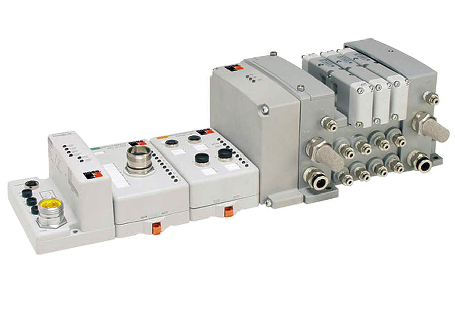
BL67 combines all the flexibility of an in-the-cabinet PLC I/O system with modularity, ruggedness and connectorization. BL67 complements the AIM™, BL20 and piconet® product families to meet the needs of unique applications, such as small machine or conveyor systems requiring IP 67 protection.
Please refer to the side and below for links to easily navigate and download ROSS Controls Serial Bus With ROSS & Turck Modular I/0 catalogs, installation instructions, and technical data. Additionally, you have the option to filter through all available options to discover Serial Bus With ROSS & Turck Modular I/0 variant that meets your requirements.
loading...
loading...
Product Overview
The ROSS Controls Serial Bus system integrates the TURCK BL67 Modular I/O platform with ROSS ISO W65 and W66 Series pneumatic valve manifolds to deliver a complete centralized fieldbus control architecture for pneumatic valve networks. The system eliminates conventional point-to-point solenoid wiring between the control cabinet and each valve, replacing it with a single fieldbus cable that carries all valve command and diagnostic data from the controller to the machine-mounted I/O node.
The BL67 hardware is the foundation of this system. It is a modular, DIN-rail or frame-mountable I/O system rated to IP67 (NEMA 1, 3, 4, 12, 13), which allows the gateway and I/O modules to be installed directly on the machine frame or conveyor structure without a protective enclosure. This eliminates the cabinet space, heat management, and wiring infrastructure that conventional centralized I/O installations require.
The system architecture consists of a gateway module that manages the fieldbus communication protocol, followed by up to 32 I/O station modules per gateway. Supported protocols include EtherNet/IP, Modbus TCP/IP, PROFIBUS-DP, PROFINET, DeviceNet, and CANopen, covering the major industrial fieldbus standards in use across North American, European, and global automotive and manufacturing facilities. ROSS valve driver modules (RPSSV16A and RPSSV32A) mount directly to the W65 and W66 valve manifold bases, providing the interface between the BL67 system and the individual solenoid valve outputs.
The BL67 platform supports both non-programmable gateways for straightforward I/O mapping and programmable gateways (designated PG in the model number) that execute IEC 61131-3 logic using CodeSys, including ladder logic. This enables edge-level logic execution within the pneumatic valve node, reducing PLC scan cycle dependencies for time-sensitive valve sequences.
Key Engineering Features
- Multi-Protocol Fieldbus Gateway Support - Single hardware platform supports EtherNet/IP, Modbus TCP/IP, PROFIBUS-DP (DPV1), PROFINET, DeviceNet, and CANopen through interchangeable gateway modules. This allows the same I/O and valve hardware to be used across plants with different PLC brands and network standards.
- IP67 Protection Class - No Enclosure Required - BL67 gateway and I/O modules carry IP67 (NEMA 1, 3, 4, 12, 13) ingress protection. They can be mounted directly on machine frames, conveyor structures, or pneumatic panels without enclosures, eliminating cabinet space requirements and reducing installation material costs.
- Modular I/O Expansion up to 32 Modules per Gateway - Each BL67 gateway supports up to 32 I/O station modules (approximately 1 meter of station length). Modules include digital inputs (PNP/NPN), digital outputs, analog inputs and outputs, temperature inputs (thermocouple and RTD), and serial communication interfaces, all on the same bus.
- Hot-Swappable Electronic Modules - BL67 electronic modules are hot swappable. A failed I/O module or valve driver module can be replaced while the gateway remains powered and the fieldbus network stays active, reducing the impact of a component failure on overall machine uptime.
- ROSS Valve Driver Modules for Direct Manifold Integration - RPSSV16A (16-output) and RPSSV32A (32-output) ROSS valve driver modules mount directly to W65 and W66 Series manifold bases. Pre-wired cable assemblies connect the valve driver to the BL67 node, eliminating individual solenoid wiring between I/O modules and manifold stations.
- Programmable Gateway Option for Edge Logic - Programmable BL67 gateways (BL67-PG-EN-IP, BL67-PG-DP, BL67-PG-EN) execute IEC 61131-3 programs using CodeSys, including ladder logic. This enables pneumatic sequence logic to run locally at the machine without dependence on the main PLC scan cycle, supporting faster and more deterministic valve actuation sequences.
- Flexible Connector Base Modules - BL67 base modules accommodate eurofast (M12), picofast (M8), M23, and minifast (7/8-16UN) field device connectors. This flexibility supports connection to a wide variety of sensors, photo eyes, limit switches, and output devices using industry-standard connectors.
- Power Feeding Modules for Segmented Power Distribution - BL67 power feeding modules (BL67-PF-24VDC) insert into the station at any point to provide a new, isolated 24 VDC supply segment for all I/O modules downstream of the power feed. This allows separate input and output power domains and supports power budget management across long stations.
- Diagnostic LED Indication at Gateway and Module Level - Each BL67 gateway and I/O module provides LED indicators for module bus communication status, fieldbus network status, and per-channel I/O state. Logical diagnostics are also accessible through the fieldbus gateway I/O map, enabling remote fault identification from the control system.
- Compatible with ROSS AIM and piconet Systems - The BL67 Serial Bus system complements the ROSS AIM (Advanced Integrated Manifold) and piconet product families. For applications requiring higher environmental protection (continuous submersion, high-pressure washdown, 100 percent humidity), fully potted AIM stations are the recommended alternative.
Technical Specifications
General Specifications
| Parameter | Specification |
| I/O Platform | TURCK BL67 Modular Industrial I/O System |
| Compatible ROSS Valve Series | W65 Series (ISO 5599-1/5599-2) and W66 Series (ISO 15407-1/15407-2) |
| Supported Fieldbus Protocols | EtherNet/IP, Modbus TCP/IP, PROFIBUS-DP (DPV1), PROFINET, DeviceNet, CANopen |
| Maximum I/O Modules per Gateway | 32 station modules per gateway (approximately 1 m station length) |
| Maximum I/O Points | Up to 8 I/O modules per station module; system I/O count limited by gateway data capacity |
| Operating Temperature | 32 to 131F (0 to 55C) operating; -13 to 185F (-25 to 85C) storage |
| Protection Class | IP67, NEMA 1, 3, 4, 12, 13 |
| Vibration | 1.0 g at 5-10 Hz (environmental); 5 g at 10-500 Hz (gateway/module spec) |
| Shock | 15 g |
| Relative Humidity | 5 to 95% non-condensing (indoor) |
| Supply Voltage | 24 VDC |
| Gateway Operating Current | Less than 600 mA from module bus (VMB) |
| Input Supply Current (VI) | Less than 4 A per power domain |
| Output Supply Current (VO) | Less than 8 A per power domain |
| Module Bus Backplane Current | Sum of all module IMB values must not exceed 1.5 A |
| Housing Material | PC-V0 (Lexan) polycarbonate; Nickel-plated brass connectors |
| Electromagnetic Compatibility | EN 61131-2 |
| Certifications | UL Listed (USA), C-UL (Canada/CSA), CE (European Union) |
Flow Performance Data
Communication module and I/O module current consumption values determine the power budget for a BL67 station. Use the TURCK I/O assistant software (available from turck.com) to verify power budget and station configuration before ordering.
| Module | IMB Current at 5V | Current from Gateway at 24V |
| BL67-GW-DPV1 (PROFIBUS-DP Gateway) | 150 mA | |
| BL67-GW-DN (DeviceNet Gateway) | 100 mA | |
| BL67-4DI-P (4 Digital Inputs PNP) | 30 mA | 9 mA |
| BL67-8DI-P (8 Digital Inputs PNP) | 30 mA | 9 mA |
| BL67-4DO-0.5A-P (4 Digital Outputs 0.5A) | 30 mA | 9 mA |
| BL67-4DO-2A-P (4 Digital Outputs 2A) | 30 mA | 9 mA |
| BL67-8DO-0.5A-P (8 Digital Outputs 0.5A) | 30 mA | 9 mA |
| BL67-2AI-V (2 Analog Inputs Voltage) | 35 mA | 10 mA |
| BL67-2AI-I (2 Analog Inputs Current) | 35 mA | 10 mA |
| BL67-2AI-TC (2 Temp Inputs Thermocouple) | 35 mA | 10 mA |
| BL67-2AI-PT (2 Temp Inputs RTD) | 45 mA | 13 mA |
| BL67-2AO-V (2 Analog Outputs Voltage) | 60 mA | 17 mA |
| BL67-2AO-I (2 Analog Outputs Current) | 40 mA | 12 mA |
| BL67-PF-24VDC (Power Feeding Module) | 30 mA | 10 mA |
Certifications & Compliance
| Certification/Standard | Detail |
| UL Listed | UL Listed for the United States market, confirming compliance with applicable UL safety standards for industrial I/O equipment. |
| C-UL Listed (CSA) | C-UL (CSA) listed for the Canadian market, satisfying Canadian Electrical Code requirements. |
| CE Marked | CE marking for European Union market compliance with applicable directives including Low Voltage Directive and EMC Directive. |
| IP67 / NEMA 1, 3, 4, 12, 13 | IEC IP67 and equivalent NEMA 1, 3, 4, 12, and 13 ingress protection, enabling machine-mounted installation without enclosures in environments exposed to dust, dirt, coolants, and incidental liquid contact. |
| EMC: EN 61131-2 | Electromagnetic compatibility per EN 61131-2 for programmable controllers, ensuring reliable communication in industrial environments with electrical noise from variable frequency drives, solenoids, and other inductive loads. |
| EtherNet/IP Conformance (ODVA) | EtherNet/IP gateway models conform to ODVA EtherNet/IP standards, ensuring interoperability with Allen-Bradley ControlLogix, CompactLogix, and other CIP-based controllers. |
Typical Applications & Industries
Machine Automation and Assembly Equipment
- Multi-axis assembly machines where 10 to 32 pneumatic valve outputs need to be controlled from a single network node, eliminating the individual solenoid wire runs from the control cabinet to each valve.
- Rotary index tables and transfer machines where the BL67 node mounts to the machine base near the pneumatic manifold, reducing the wiring length from fieldbus cable to zero individual solenoid wires.
- Automated test stands where mixed digital I/O (sensor inputs and valve outputs) combined with analog I/O (pressure transducers, flow sensors) are all wired to a single BL67 node on the test fixture.
- Press and stamping auxiliary systems where valve control, safety interlock monitoring, and part-present sensing are consolidated in a single machine-mounted IP67 node.
Conveyor Systems and Material Handling
- Conveyor diverter, pusher, and lifter control where BL67 nodes mount along the conveyor line at the point of use, with each node controlling 4 to 32 pneumatic actuators from a single EtherNet/IP or PROFIBUS connection.
- Accumulation conveyor zones where each zone's pneumatic valve and proximity sensor inputs are managed by a single BL67 node, simplifying zone-by-zone control architecture.
- Small machine and conveyor systems requiring IP67 protection where the BL67 complements or replaces the AIM, BL20, and piconet product families for applications that do not require full submersion or high-pressure washdown protection.
- Palletizing and depalletizing stations where multiple pneumatic grippers, clamps, and pushers on a single station are all controlled through one BL67 fieldbus node.
Automotive Body Shop and Paint Line
- Body shop weld gun and clamp control where PROFIBUS or EtherNet/IP networks connect multiple BL67 nodes along body line transfer tooling, each controlling a cluster of W65 or W66 Series valves.
- Paint line equipment where BL67 nodes withstand paint booth environments (within IP67 humidity limits) and control pneumatic actuators for door opening mechanisms, part rotation systems, and spray booth gates.
- End-of-line test stations where mixed valve control and sensor monitoring at each test position are managed by a single programmable BL67 node executing local test sequence logic.
Industry 4.0 and Smart Manufacturing
- Edge computing applications where programmable BL67 gateways execute IEC 61131-3 ladder logic locally at the pneumatic valve node, reducing main PLC cycle time dependencies for high-speed valve sequences.
- Condition monitoring integration where analog I/O modules on the BL67 node connect to pressure transducers and flow sensors at each valve manifold, feeding cycle count, pressure trend, and response time data upstream to MES systems.
- Flexible manufacturing systems where recipe-based valve sequence management is stored and executed at the BL67 node level, enabling product changeovers without PLC program downloads.
Ordering and Model Number Configuration
The ROSS Serial Bus system is assembled from separately ordered components: a BL67 gateway module (selecting the desired fieldbus protocol), I/O modules (digital inputs, digital outputs, analog I/O), optional specialty modules (serial communication, CANopen interface), base modules (selecting connector type and pin count), and ROSS valve driver modules for W65 and W66 manifold integration. The selection process follows six sequential steps.
|
BL67 System Selection Sequence:
Step 1: Select Communication Gateway Module BL67-GW-EN-IP EtherNet/IP Gateway (non-programmable) BL67-PG-EN-IP EtherNet/IP Gateway (programmable, IEC 61131-3 CodeSys) BL67-GW-EN Modbus TCP/IP Gateway (non-programmable) BL67-PG-EN Modbus TCP/IP Gateway (programmable) BL67-GW-DPV1 PROFIBUS-DP Gateway (non-programmable) BL67-PG-DP PROFIBUS-DP Gateway (programmable) BL67-GW-EN-PN PROFINET Gateway BL67-GW-DN DeviceNet Gateway BL67-GW-CO CANopen Gateway
Step 2: Select I/O Modules BL67-4DI-P 4-point digital input, PNP BL67-8DI-P 8-point digital input, PNP BL67-4DO-0.5A-P 4-point digital output, 0.5A PNP BL67-4DO-2A-P 4-point digital output, 2A PNP BL67-8DO-0.5A-P 8-point digital output, 0.5A PNP BL67-16DO-0.5A-P 16-point digital output, 0.5A PNP BL67-8XSG-P 8-in/8-out combination, 0.5A PNP BL67-2AI-V 2-channel analog input, voltage BL67-2AI-I 2-channel analog input, current BL67-2AI-TC 2-channel temperature input, thermocouple BL67-2AI-PT 2-channel temperature input, RTD BL67-2AO-V 2-channel analog output, voltage BL67-2AO-I 2-channel analog output, current
Step 3: Select Optional Specialty Modules BL67-1RS232 Serial communication module, RS-232 BL67-1RS485/422 Serial communication module, RS-485/422 BL67-1SSI SSI encoder interface module BL67-PF-24VDC Power feeding module (24 VDC isolation point)
Step 4: Select Base Modules (connector type for field devices) BL67-B-2M12 eurofast (M12) 2-connector base, 2 pins each BL67-B-4M12 eurofast (M12) 4-connector base BL67-B-4M8 picofast (M8) 4-connector base BL67-B-8M8 picofast (M8) 8-connector base BL67-B-1M23 M23 1-connector base, 12 pins BL67-B-1RSM minifast 5-wire power scheme
Step 5: Select ROSS Valve Driver Module for W65/W66 Manifolds RPSSV16A 16-output valve driver (T1 designation) RPSSV32A 32-output valve driver (T2 designation) |
The BL67 gateway module addresses on the network using rotary switches. DeviceNet and CANopen: address 0-63, two switches (10's and 1's digit). PROFIBUS-DP: address 1-125, three switches. Ethernet gateways support BootP, DHCP, or static IP address assignment.
Maximum station length is 32 I/O modules per gateway (approximately 1 m). High-density and analog modules may reduce this count due to data bandwidth limits. Use the free TURCK I/O assistant software (turck.com) to verify station configuration and power budget before finalizing the order.
The sum of module bus current (IMB) for all modules in a station must not exceed 1.5 A. If the station exceeds this limit, insert BL67-PF-24VDC power feeding modules to create isolated power segments.
ROSS valve driver modules RPSSV16A and RPSSV32A connect to the BL67 node via pre-wired cable assemblies and mount directly to W65 and W66 Series manifold base end plates.
Programmable gateway models (prefix PG in model number) support IEC 61131-3 programming using CodeSys software, including ladder logic. Programming cable XN-PS2-CABLE connects the BL67 or BL20 system to the I/O assistant software.
For systems requiring higher IP protection (continuous submersion, 100% humidity, high-pressure washdown), ROSS AIM (Advanced Integrated Manifold) stations are the recommended alternative. BL67 is intended for industrial environments with incidental liquid exposure within the IP67 specification.
Accessories
ROSS W65 Series ISO 5599 Valve Manifolds
ISO 5599-1 and 5599-2 compliant pneumatic valve manifolds in Sizes 1, 2, and 3 for integration with the BL67 Serial Bus system using RPSSV16A or RPSSV32A valve driver modules. Manifolds support 2 to 32 valve stations with collective wiring end plates (25-pin D-Sub, 19-pin round, M23 12-pin) and Serial Bus communication-ready bases.
ROSS W66 Series ISO 15407 Valve Manifolds
ISO 15407-1 and 15407-2 compliant compact pneumatic valve manifolds in Size 00 (18mm) and Size 0 (26mm) for tight-space applications. Compatible with BL67 Serial Bus valve driver modules for full fieldbus integration.
I/O Assistant Software
Free TURCK I/O assistant software (available from turck.com) enables virtual BL67 station configuration on a PC before purchasing hardware. The software verifies power budget, module count limits, and data size restrictions, generating error notifications automatically via the Station - Verify function. Required for commissioning complex multi-module configurations.
Programming Cable
XN-PS2-CABLE connects BL67 and BL20 gateway systems to the I/O assistant and CodeSys programming environments for configuring programmable gateway models.
Module Labeling Strips
BL67-Label/DIN-A4-50-PCS: DIN A4 format label sheets for labeling BL67 electronic modules with I/O point assignments. Improves maintenance traceability in installations with multiple identical-looking modules.
Related Products & Accessories
- ANSI Valves W70 and W74 Series - ANSI-standard base mounted directional control valves in spool/sleeve (W70) and poppet (W74) construction, sizes 1 through 20. https://www.rosscontrols.com/en/series/245-ansi-valves-w70-w74-series
- SAE Valves 80 and 84 Series - SAE J2051-compliant base mounted directional control valves in spool/sleeve (80) and poppet (84) construction, SAE sizes 125 through 500. https://www.rosscontrols.com/en/series/246-sae-valves-80-84-series
- 21 Series Classic Directional Control Valves - Inline poppet directional control valves for standard, low, and high temperature applications, port sizes 1/4" to 1-1/2". https://www.rosscontrols.com/en/series/231-low-high-temperatures-classic-21-series
- 2759 Series Low/High Temperature DIN and M12 Valves - Inline poppet valves with DIN and M12 connections for extreme temperature applications (-40F to 300F), TUV SIL 2 certified. https://www.rosscontrols.com/en/series/2759-lowhigh-temperatures-din-m12-connection-21-series
- Electrical Connectors - DIN EN 175301-803 and M12 connectors, prewired assemblies, and lighted indicators for ROSS solenoid valves. https://www.rosscontrols.com/en/series/91-electrical-connectors
Frequently Asked Questions (FAQ)
Q: What is the BL67 system and why is it used with ROSS valves?
A: The BL67 is a TURCK modular I/O system designed for machine-mounted installation without enclosures, rated to IP67. ROSS integrates the BL67 platform with its W65 and W66 Series ISO pneumatic valve manifolds to provide a complete centralized fieldbus control solution. Instead of running individual solenoid wires from the control cabinet to each valve, a single fieldbus cable connects the controller to the BL67 node on the machine, where ROSS valve driver modules then drive the valve solenoids directly at the manifold.
Q: Which fieldbus protocols does the BL67 system support?
A: The BL67 supports EtherNet/IP, Modbus TCP/IP, PROFIBUS-DP (DPV1), PROFINET, DeviceNet, and CANopen through interchangeable gateway modules. The gateway module in a BL67 station is the only protocol-specific component; all I/O modules and valve driver modules are protocol-independent and work with any gateway.
Q: How many I/O modules can be connected to one BL67 gateway?
A: Up to 32 station modules can be assembled on a single BL67 gateway (approximately 1 meter of station length). The actual number may be lower for configurations that include high-data-volume analog or specialty modules, due to gateway data capacity limits. Use the TURCK I/O assistant software to verify the maximum configuration before ordering.
Q: Can the BL67 be installed directly on the machine without an enclosure?
A: Yes. The BL67 gateway and all I/O modules carry IP67 (NEMA 1, 3, 4, 12, 13) protection, enabling installation directly on machine frames, conveyor structures, or pneumatic distribution panels without enclosures. This eliminates the cost and space requirements of control cabinet installation for field I/O. The system is intended for environments with dirt, dust, coolants, and incidental liquid exposure. It is not intended for continuous submersion, 100 percent humidity environments, or high-pressure washdown applications.
Q: What are the RPSSV16A and RPSSV32A valve driver modules?
A: The RPSSV16A and RPSSV32A are ROSS-specific valve driver modules that mount directly to W65 and W66 Series manifold bases. The RPSSV16A provides 16 valve solenoid output channels; the RPSSV32A provides 32 channels. They connect to the BL67 node via factory-assembled cable assemblies, eliminating individual solenoid wiring between the I/O system and each valve station. The T1 designation in a manifold model number indicates RPSSV16A compatibility; T2 indicates RPSSV32A.
Q: What ISO valve series are compatible with the BL67 Serial Bus system?
A: The ROSS BL67 Serial Bus system is designed specifically for the ROSS W65 Series (ISO 5599-1 and 5599-2) and W66 Series (ISO 15407-1 and 15407-2) valve manifolds. The W65 covers ISO Sizes 1, 2, and 3 for medium to high flow applications. The W66 covers ISO Sizes 00 (18mm) and 0 (26mm) for compact installations.
Q: What is the difference between programmable and non-programmable BL67 gateways?
A: Non-programmable gateways (for example, BL67-GW-EN-IP, BL67-GW-EN, BL67-GW-DPV1) map fieldbus network data directly to I/O module states. The PLC or controller sends valve commands as output data and receives sensor states as input data. Programmable gateways (BL67-PG-EN-IP, BL67-PG-DP, BL67-PG-EN) add a local IEC 61131-3 execution engine using CodeSys, allowing ladder logic or other IEC programs to run at the I/O node level. This enables pneumatic valve sequences to execute locally without a round-trip to the main PLC, which reduces latency for time-critical sequences.
Q: How is the BL67 node addressed on the network?
A: DeviceNet and CANopen nodes are addressed using two rotary switches (0-63 range). PROFIBUS-DP nodes use three rotary switches (1-125 range). Ethernet-based gateways (EtherNet/IP, Modbus TCP, PROFINET) support dynamic addressing via BootP or DHCP, or static IP address entry. The addressing switches are accessible on the gateway module face.
Q: What is the module bus current limit and why does it matter?
A: The sum of all module bus current (IMB) values for all modules in a BL67 station must not exceed 1.5 A. If the station configuration exceeds this limit, a BL67-PF-24VDC power feeding module must be inserted to create a new isolated power segment. The TURCK I/O assistant software automatically checks this limit during station configuration and generates an error notification when the limit is exceeded.
Q: Can the BL67 system accommodate mixed digital and analog I/O on the same node?
A: Yes. BL67 digital input, digital output, analog input, analog output, and temperature input modules can all coexist in the same station on any gateway type. There is no restriction on mixing I/O types. The total station size (32 modules maximum) and module bus current limit (1.5 A) are the governing constraints, not I/O type combinations.
Q: What connector types are available for field device wiring?
A: BL67 base modules accommodate eurofast M12 (2-pin, 4-pin, 5-pin), picofast M8 (4-pin, 8-pin), M23 (12-pin, 19-pin), and minifast connectors. Connector selection depends on the field device connector type. Eurofast M12 is the most common choice for sensors and actuators in industrial environments.
Q: Is the BL67 system suitable for automotive paint booth environments?
A: BL67 nodes in automotive paint booth environments must be evaluated against the specific environmental conditions present. The IP67 rating covers dust-tight and temporary immersion conditions. If the paint booth involves solvent misting, chemical exposure, or humidity near or at 100 percent, the BL67 may not be appropriate. ROSS AIM (fully potted) stations are recommended for applications that exceed the BL67 environmental limits.
Q: How do power feeding modules affect the station design?
A: A BL67-PF-24VDC power feeding module inserted at any point in the station provides a fresh, isolated 24 VDC supply for all I/O modules to its right. This allows the input power (VI) and output power (VO) segments on either side of the power feed to operate as independent power domains, important for applications where solenoid valve outputs and sensor inputs need separate power sources for noise isolation or protection circuit reasons.
Q: What software tools are available for BL67 system design and commissioning?
A: The TURCK I/O assistant software (free download from turck.com) provides a virtual BL67 station builder that checks power budgets, module count limits, and data size restrictions before ordering hardware. A programming cable (XN-PS2-CABLE) connects the BL67 system to the I/O assistant for configuration and to CodeSys for programming of programmable gateway models.
Installation & Maintenance Guidelines
- Select the gateway model for the required fieldbus protocol before any other installation steps. The gateway is the only protocol-specific component in the BL67 station; all I/O and valve driver modules are protocol-independent. Changing the protocol after installation requires only replacing the gateway module.
- Use the TURCK I/O assistant software to verify the planned station configuration before purchasing hardware. Input all planned modules and verify that module bus current (IMB sum less than 1.5 A) and station length (32 modules maximum) are within limits. Address any violations by adding BL67-PF-24VDC power feeding modules or splitting the station.
- Mount the BL67 gateway on the machine frame or DIN rail at the point closest to the valve manifold. Shorter cable distances between the BL67 node and the ROSS valve driver modules reduce potential for electrical noise pickup on the valve driver cables.
- Set the network address on the gateway rotary switches before applying power. DeviceNet and CANopen addresses range from 0 to 63 using two switches (10's and 1's digit). PROFIBUS-DP addresses range from 1 to 125 using three switches. Ethernet gateways use BootP, DHCP, or static IP as configured in the controller or network DHCP server.
- For Ethernet gateways (EtherNet/IP, Modbus TCP, PROFINET), assign a static IP address through the BootP server or controller configuration tool before commissioning. Dynamic DHCP addresses change on power cycle, which disrupts the controller's connection to the node.
- Connect the field power supply (24 VDC) to the gateway power connector before assembling I/O modules to the station. Verify supply voltage is within the 24 VDC nominal specification (typically 19.2 to 28.8 VDC). Voltage excursions outside this range will cause module faults.
- Assemble I/O modules from left to right on the DIN rail or frame, starting from the gateway. Verify each module bus connector is fully engaged before proceeding to the next module. Partial engagement causes intermittent communication faults that are difficult to diagnose after installation.
- Install BL67-PF-24VDC power feeding modules at any point where the cumulative module bus current to the left of that point approaches the 1.5 A limit, or where separate input and output power domains are required. Power feeding modules provide full 4 A input (VI) and 8 A output (VO) capacity for all downstream modules.
- Connect base modules to electronic modules before mounting in the station. Verify the base module connector type (M12, M8, M23, minifast) matches the field device connectors that will be attached. Mating connector types must be compatible; mixed connector families will not mate properly.
- Route field device cables (sensor inputs, output device cables) away from high-power wiring such as motor drives, solenoid output cables, and welding equipment supply lines. Electromagnetic interference from these sources can cause false I/O states on unshielded sensor inputs. Use shielded cables for analog I/O module connections.
- Connect the ROSS valve driver module (RPSSV16A or RPSSV32A) to the BL67 node using the pre-wired factory cable assembly. Verify that the cable assembly model matches the valve driver module type and the BL67 I/O module output configuration. Incorrect cable assemblies will result in incorrect valve output mapping.
- After completing all hardware connections, apply power and use the BL67 diagnostic LEDs to verify gateway communication (network status LED steady green = active connection) and I/O module bus status (module bus LED steady green = healthy bus). Individual I/O module LEDs indicate per-channel status.
- Commission each valve output by forcing the output state through the fieldbus controller or through the I/O assistant software. Verify the correct valve actuates and that the solenoid indicator light (if present on the manifold) illuminates. Document any mismatched valve-to-output assignments and correct the output address mapping.
- For programmable gateways, download and test the IEC 61131-3 application program using the CodeSys environment connected through the programming cable before connecting the BL67 node to the production fieldbus network. Test all valve sequences in simulation mode or with the valve manifold isolated from actuator loads.
- Label each I/O module on the station with the module model number and the field device assignment for each channel. Attach the BL67-Label/DIN-A4-50-PCS labeling strips to the module faces. Clear channel labeling reduces commissioning time and accelerates fault diagnosis during production operation.
Warranty & Global Support
ROSS Controls provides a one-year warranty on all Serial Bus system components, covering defects in material and workmanship from the date of purchase.
TURCK BL67 components carry TURCK's standard warranty terms. For TURCK warranty details by product type (12-month, 18-month, 24-month, 5-year, or lifetime), refer to the TURCK warranty terms included with BL67 products or available from turck.com.
Global ROSS technical support is available through offices in the United States (Ferndale, Michigan headquarters), Canada, Brazil, Germany, France, United Kingdom, India, China, and Japan. Contact ROSS at (800) 438-7677 or rosscontrols.com.
TURCK technical support for BL67 hardware, I/O assistant software, and programming questions is available from TURCK Inc. at turck.com or the TURCK USA office in Minneapolis, Minnesota.
Download Catalog: https://www.rosscontrols.com/en/documents/3/serial-bus-system-with-turck-modular-i-o
Download Documents
Serial Bus
