




Pneumatic Safety Solutions for Press Metal Forming
A single 1,000-ton stamping line produces enough stored mechanical and pneumatic energy to cause a fatality in milliseconds if a clutch fails to disengage, a counterbalance loses pressure, or a die cushion releases unexpectedly. Stopping-time degradation, pressure intensification, and uncontrolled slide motion are not theoretical risks. They are the precise failure modes that drive the regulatory framework governing every press operation in North America and Europe. For the engineers who design press control systems and the safety managers who certify them, the pneumatic and hydraulic valves controlling clutch, brake, counterbalance, die cushion, and air distribution functions are not commodity components. They are the safety-rated devices that determine whether a press meets ANSI B11.1, ANSI B11.2, OSHA 29 CFR 1910.217, ISO 16092, and CSA Z142:10.
ROSS Controls has manufactured pneumatic valves since 1921 and is the first valve manufacturer to introduce double valve technology to the press industry. ROSS Controls has been the global leader in pneumatic and hydraulic safety solutions for mechanical power presses since 1921, with a clutch/brake double valve application history that pre-dates today's certification standards and helped shape them. ROSS engineers serve on ANSI B11 safety standards committees, and the company's poppet valve architecture, dynamic monitoring, and ROSS/FLEX custom engineering program are deployed in stamping plants across automotive, appliance, aerospace, electrical lamination, and heavy fabrication sectors. This page explains how ROSS valve technology addresses the specific challenges of clutch/brake control, counterbalance regulation, energy isolation, load holding, and air distribution in press metal forming, and identifies the ROSS product series matched to each function.
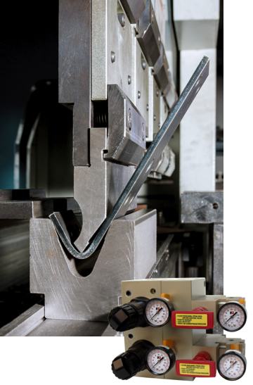
Why Press Metal Forming Operations Demand Precision Fluid Power Control
Press metal forming combines high stored energy, repetitive duty cycles, and tight cycle-time targets in a single machine. The pneumatic and hydraulic systems that control press motion must perform reliably under conditions that destroy general-purpose industrial valves. Five operating realities dictate valve selection.
Stopping-time integrity under single-component failure.
Federal and consensus standards require that a single failure inside a clutch/brake valve must not significantly increase the press stopping time and must inhibit further operation if such a failure occurs. OSHA 29 CFR 1910.217(b)(7)(xi) mandates this for air-clutch machines. ANSI B11.1 reinforces it for mechanical power presses, and ANSI B11.2 extends equivalent logic to hydraulic and pneumatic presses. A single 3/2 directional valve cannot satisfy this requirement, regardless of size or quality, because no single-channel device can detect its own failure during the cycle in which the failure occurs.
Contamination from forming lubricants, slug debris, and ambient particulate.
Stamping plants generate aerosolized drawing compounds, oil mist from clutch packs, slug fragments from progressive dies, and airborne scale from hot forming. Spool valves with close-tolerance lapped fits are vulnerable to silting and stiction in this environment. Poppet valves with self-cleaning seal geometry tolerate the same contaminant load without performance degradation.
High-cycle duty in the tens of millions of strokes.
Automotive body-in-white stamping lines run 12 to 18 strokes per minute across two or three shifts. Over a five-year service interval, a clutch/brake valve will see tens of millions of cycles. Valve seal designs that depend on sliding contact wear at a predictable rate. Poppet seals that engage and disengage without lateral motion maintain their original sealing pressure for the life of the valve.
Shock loading and pressure spikes from die impact.
Each press stroke produces two distinct shock events: deceleration when the upper die contacts the workpiece, and reversal as the slide retracts. A reactive pressure regulator cannot keep up. An intelligent counterbalance system that monitors pressure transducer feedback and actively fills and dumps air at top dead center can.
Hazardous energy during die change, jam clearance, and maintenance.
OSHA 29 CFR 1910.147 (the Control of Hazardous Energy standard) and ANSI/ASSE Z244.1-2024 govern lockout/tagout (LOTO) for stored pneumatic and hydraulic energy. A press cannot be considered isolated until residual air has been dumped from clutch reservoirs and until the dump path itself is locked in the open position. Energy isolation valves with full exhaust ports and the ability to be locked out are mandatory, not optional.
These five realities determine what a press control valve must do. The remainder of this page explains how ROSS valve architecture answers each one.

ROSS Valve Technology for Press Metal Forming Conditions
The ROSS poppet valve architecture is the foundation for every safety-rated and standard product applied to press metal forming. Its operating principles are matched to the specific failure modes that occur on a stamping line.
In a poppet valve, the sealing element is pressed against a flat or conical seat by spring force or pilot pressure, and lifts straight off the seat to allow flow. There is no lateral sliding motion between the seal and its mating surface. This single architectural choice produces the performance characteristics that matter on a press. Stiction does not develop, because there is no extended sliding contact that can dry out, varnish, or trap particulate. Wear does not progress, because the seal does not abrade against a bore wall. Response time stays consistent across millions of cycles, because the sealings are wear compensating.
Poppet valves are inherently dirt tolerant. The flow passages around the poppet are large compared to the clearance gaps in a spool valve, and the highest fluid velocity in the valve occurs at the moment the poppet first lifts, when the throat area is smallest. That high-velocity flow scrubs the seat clean of any contaminant that has settled during the off cycle. In a stamping environment loaded with drawing-compound aerosol and slug fines, this self-cleaning behavior is the difference between a valve that holds calibrated stopping time for years and one that drifts within months.
The ROSS poppet design also produces fast, repeatable shifting. The exhaust poppet, inlet poppet, and piston poppet surface areas are sized so that pilot pressure and spring force generate consistent shifting force in both directions across the full operating pressure range of 30 to 150 psi. Response times stay within specification from the first cycle to the last, which is the prerequisite for the 100 to 125 millisecond fault-detection window that defines Category 4 PLe performance under ISO 13849-1.
For press applications that require higher flow rates than a single poppet provides, ROSS offers 27 Series valves. These are appropriate for transfer feed actuation, die clamping, and automation circuits where the duty cycle and contamination level are lower than the clutch/brake or counterbalance circuits, but where high flow and modular manifold mounting are required. Spool valves are not used for safety-critical clutch/brake.
Elastomer materials in ROSS press valves are specified for an operating temperature range of 32°F to 185°F, which covers ambient stamping floor conditions and the elevated temperatures that develop near hot forming presses, induction heaters, and trim presses operating downstream of an automation line.
Press Metal Forming Application Solutions
ROSS products are organized around the discrete control functions of a modern press line. Each application area has specific performance requirements and a specific ROSS solution.
Clutch and Brake Control
Clutch and brake control is the highest-risk pneumatic function on a mechanical power press. The valve must couple the flywheel energy to stop slide motion within the calculated stopping time. A failure in the open position can cause a repeat stroke. A failure in the closed position locks the press out of cycle. Single-channel valves cannot detect either failure mode in time to prevent a repeat stroke.
The ROSS DM2 Series D and 35 Series SERPAR double valves solves this with a redundant crossflow architecture and dynamic self-monitoring. Two independent valve elements are arranged so that both must shift together within a defined time window. If they do not, the monitoring system detects the asynchronous condition within 100 to 125 milliseconds, exhausts downstream air, and locks the press out of further operation until a manual reset is performed. The DM2D Series valve has dynamic memory, meaning fault information is retained through power-down and power-up cycles. There is no automatic reset on air or electrical recycling, which prevents an operator from clearing a fault by simply restoring power.
Key Benefits
- Category 4 PLe performance under ISO 13849-1, the highest performance level defined by the standard
- Fault detection within 100 to 125 ms
- Dynamic memory prevents fault clearing through power cycling
- Patented SERPAR crossflow passages preserve safety function under single-element failure
- Base-mounted construction simplifies field replacement and reduces piping joints
Typical Applications
- Mechanical power press clutch and brake control
- Single-stroke and continuous-stroke press operation
- Transfer press station synchronization
- Progressive die press lines
- Hot forming and warm forming press control
Counterbalance Pressure Control
Counterbalance cylinders carry the weight of the slide, ram, and upper die assembly so that the press drive is not loaded by gravity. If counterbalance pressure is too low, drive components carry excess load and tolerances open up. If pressure is too high, the slide accelerates on the upstroke and shock-loads the gibs and connection points. Standard OEM counterbalance regulators react slowly to pressure changes during die changes or when a stroke pattern shifts, and they cannot dump excess pressure actively.
The ROSS Automatic Counterbalance System uses a closed-loop pressure control architecture with adjustable fill and dump valves driven by pressure transducer feedback at top dead center. The system maintains counterbalance pressure within ±1 psi of the setpoint across the full operating range, regardless of die weight changes or production rate variations. A unique check valve geometry prevents reverse flow into the plant air system when downstream pressure exceeds upstream pressure during a stroke. The system is designed to integrate with safety controllers, and dual-channel solenoid control with diagnostic feedback is standard for installations using a Rockwell Automation GuardLogix safety PLC or equivalent.
Key Benefits
- Counterbalance pressure can be held within ±1 psi of setpoint across cycle
- Active fill and dump for fast response to die-weight changes
- No backflushing into plant air supply
- Dual-channel control compatible with safety PLCs
Typical Applications
- Single-action mechanical press counterbalance
- Double-action press counterbalance
- Transfer press counterbalance with multiple cylinders
- Die change pressure recalibration
Die Cushion Control
Die cushions provide controlled blank holder force during deep drawing and stretch forming, and absorb shock at the bottom of the stroke. The cushion air supply must hold pressure under load, dump quickly at the end of the stroke to allow controlled return, and isolate from the plant air system during slide retract to prevent unintended cushion charging.
Key Benefits
- Positive load holding under full press tonnage
Typical Applications
- Deep-drawn body panel stamping
- Stretch forming of aluminum and high-strength steel
- Cushion-assisted progressive die operation
- Pneumatic die cushions on mechanical presses
Air Distribution for Multi-Circuit Presses
A modern press carries between four and ten distinct pneumatic circuits: clutch and brake, counterbalance, mechanical lockout, transfer feed, die clamping, automation actuators, blow-off, and lubrication. Distributing plant air to each circuit through scattered field-mounted regulators creates leak points, complicates lockout, and makes diagnostic troubleshooting slow. A centralized air distribution manifold consolidates these functions in a single accessible location.
ROSS Air Distribution Manifolds are configured from individual blocks that can combine a pressure regulator, an integral check valve, a station lockout valve, and an independent exhaust per circuit. Blocks connect together to build the manifold to the press's specific circuit count. Each station can be locked out independently for service of one circuit while the rest of the press remains powered, supporting component lockout per ANSI/ASSE Z244.1-2024.
Key Benefits
- One accessible location for all pneumatic regulation and isolation
- Independent regulation, check, and lockout per circuit
- Modular construction supports field expansion
- Reduced fitting count lowers leak rate and maintenance hours
- lockout compatible with ANSI/ASSE Z244.1 procedures
Typical Applications
- Mechanical press main pneumatic distribution
- Transfer press multi-station control
- Tandem and progressive press lines
- Tilt table, de-stacker, and feed mechanism control
Energy Isolation and Jam Clearance
Energy isolation is required before any maintenance or jam-clearance task that places personnel inside the press envelope. OSHA 29 CFR 1910.147 and ANSI/ASSE Z244.1-2024 require positive isolation, residual energy dump, and a lockable means of preventing re-energization. For pneumatic systems, this means a key-locked valve that vents downstream air to atmosphere through a high-flow exhaust path.
The ROSS L-O-X Series provides this function with a manually operated three-position valve: In the lockout position, the supply port is positively blocked, the downstream port is connected to a full-flow exhaust silencer, and the operating handle accepts a hasp or lock. The L-O-X with EEZ-ON Soft Start integrates a slow-fill valve that bleeds pressure back into the system gradually when the lockout is released, preventing actuator slam during re-energization.
Key Benefits
- Positive supply blocking and downstream exhaust in a single device
- Only lockable in the blocked and exhaust position. Soft-start option prevents pressure spike on re-energization
- Visual position indication confirms lockout state
- Compatible with lockout per ANSI/ASSE Z244.1-2024
Typical Applications
- Pre-shift press energy isolation
- Die change lockout
- Jam clearance and stuck-die recovery
- Scheduled maintenance lockout
- Group lockout for multi-trade service work
ROSS Controls Product Solutions for Press Metal Forming
The following ROSS product series are matched to the discrete control functions of a press metal forming line. Each entry explains the product's role on a press and links to the published series page or catalog document on rosscontrols.com.
-
DM2 Series D Double Valves: Self-Monitored Clutch and Brake Control
The DM2 Series D is a base-mounted, dual-element 3/2 double valve with patented SERPAR crossflow passages and integral dynamic monitoring. It is engineered specifically for clutch and brake control on mechanical power presses and meets Category 4 PLe under ISO 13849-1, with fault detection in 100 to 125 ms and dynamic memory that retains fault state through power-down.
-
DM2 Series D (CRN): Clutch/Brake Control for Canadian Installations
The CRN-registered version of the DM2 Series D meets the documentation and registration requirements of Canadian provincial pressure-equipment authorities. It is functionally equivalent to the standard DM2 Series D and is the appropriate selection for press installations in Canadian facilities subject to CSA Z142:10.
-
SERPAR Crossflow 35 Series Double Valves: Self-Monitored Clutch and Brake Control
The SERPAR Crossflow 35 Series double valves are available with either external Electric – Pneumatic or internal Pneumatic monitoring with port sizes from ½ inch to 2 inch. The SERPAR® double valve is designed to provide control of clutch/brake mechanisms on mechanical stamping presses as well as other safety applications, such as alternative lockout systems for energy isolation.
-
L-O-X 15 Series Lockout Valves: Pneumatic Energy Isolation
The L-O-X 15 Series is a manually operated three-position lockout valve that blocks supply, exhausts downstream pressure, and accepts a lock or hasp only when in the locked out position. It is the standard ROSS solution for pneumatic energy isolation on press metal forming equipment under OSHA 29 CFR 1910.147 and ANSI/ASSE Z244.1-2024.
-
L-O-X with EEZ-ON Soft Start, 15 Series: Lockout with Controlled Re-Energization
The L-O-X with EEZ-ON Soft Start combines lockout isolation with a soft-start valve that gradually pressurizes the downstream system on release. This eliminates the actuator slam and pressure spike that occur when a fully exhausted system is re-energized at full plant pressure, and it is the recommended configuration for presses with large counterbalance volumes or accumulator-backed circuits.
-
L-O-X 27 Series Piloted Lockout: Remote Energy Isolation
The 27 Series Piloted L-O-X provides the same isolation function as the 15 Series, with the supply valve actuated by a remote pilot signal so that the manual lockout handle can be located at a guard door, control pendant, or single-point lockout station rather than at the valve body itself. This is appropriate for presses with overhead or otherwise inaccessible main air entry.
-
19 Series Pilot-Operated Check Valves: Load Holding for Cushions and Counterbalance
The 19 Series pilot-operated check valves are inline and right-angle configurations engineered for positive load holding. On a press, they hold die cushion charge against full press tonnage during the working stroke, hold counterbalance pressure during emergency stop, and lock the slide in position during stuck-die jam-clearance procedures.
-
27 Series Pilot-Operated Check Valves with Pressure Relief: Protected Load Holding
The 27 Series pilot-operated check valves are available with integral pressure relief, which protects upstream components from pressure intensification when a downstream cylinder is blocked and external force is applied.
Regulatory Compliance and Safety Standards
Press metal forming is governed by a layered framework of federal regulations, consensus standards, and international harmonized standards. The standards in the table below are the C-Type and B-Type standards that apply directly to pneumatic and hydraulic control of clutch, brake, counterbalance, die cushion, and energy isolation functions.
| Standard | Scope | ROSS Solution |
|---|---|---|
| OSHA 29 CFR 1910.217 | U.S. federal standard for mechanical power press operation, including air-clutch machine control reliability | DM2 Series D double valves with dynamic monitoring meet the air-clutch control reliability requirements at 1910.217(b)(7)(xi) |
| OSHA 29 CFR 1910.147 | U.S. federal Control of Hazardous Energy (lockout/tagout) standard | L-O-X 15 and 27 Series lockout valves provide positive isolation, exhaust, and padlock-rated lockout |
| ANSI B11.1 | U.S. consensus safety standard for mechanical power presses | DM2 Series D double valves meet the clutch/brake valve requirements; ROSS counterbalance, air distribution, and lockout systems support overall press compliance |
| ANSI B11.2 | U.S. consensus safety standard for hydraulic and pneumatic power presses | ROSS pilot-operated check valves and 5/2 crossmirror double valves support load holding and return while meeting stop-time integrity requirements |
| ANSI/ASSE Z244.1-2024 | U.S. consensus standard for the control of hazardous energy (lockout, tagout, and alternative methods) | L-O-X Series and air distribution manifolds with integral lockout support single-point lockout procedures |
| ISO 13849-1 | International standard defining performance levels for safety-related parts of control systems | DM2 Series D is rated Category 4 PLe, the highest performance level defined |
| ISO 16092-3 | International machine tool safety standard for hydraulic presses | ROSS double valves and pilot-operated check valves support the load holding and stop-function requirements |
| ISO 16092-4 | International machine tool safety standard for pneumatic presses | DM2 Series D and ROSS counterbalance products meet the dynamic monitoring and pressure control requirements |
| CSA Z142:10 | Canadian code for power press operation | DM2 Series D (CRN) is registered for Canadian provincial pressure equipment requirements |
The C-Type standards in this list (ANSI B11.1, ANSI B11.2, ISO 16092-3, ISO 16092-4, CSA Z142:10) define mandatory minimum requirements for press safety systems, and they cannot be reduced through risk assessment alone. The valve-level requirements they specify, including redundancy, dynamic monitoring, fail-to-safe behavior on single-component failure, and stopping-time integrity, are met by the ROSS DM2 Series D for clutch and brake control and supported by the ROSS L-O-X and pilot-operated check valve product lines for energy isolation and load holding. The ROSS Crossmirror 5/2 Dual Safety Valve provide dual safe position for cylinder presses.
ROSS provides documentation packages for each product series that include published performance data, third-party certification references where applicable, and installation and operation instructions sufficient to support a regulatory audit or a third-party safety integrity assessment under TÜV, UL, or comparable certification bodies. ROSS engineers serve on ANSI B11 standards committees, and the company's product roadmap is aligned with the current revision cycles of ANSI B11.1, ANSI B11.2, and the ISO 16092 series.
ROSS/FLEX: Custom Solutions for Press Metal Forming Applications
Standard valve products fit the majority of press applications, but every stamping plant has at least a few presses with non-standard counterbalance volumes, unusual port routing, retrofit constraints from a 30-year-old frame, or integrated function requirements that a catalog product does not match exactly. The ROSS/FLEX program addresses these applications by repackaging the same proven internal components used in standard ROSS products into a custom external configuration, engineered and built to the press's specific requirements.
The ROSS/FLEX engineering team develops custom valve assemblies in days rather than weeks. Because the internal components are already qualified through ROSS production testing, the custom assembly inherits the life-cycle and performance data of the standard product. There is no new component qualification required, and there is no extended sample-and-test cycle.
Four ROSS/FLEX configurations are common in press metal forming.
- The first is custom counterbalance valve packages for large multi-cylinder presses, where the standard counterbalance system needs additional flow capacity, dedicated pressure-correction circuits per cylinder, or integration into a tight envelope on the press frame.
- The second is integrated clutch, brake, and counterbalance manifolds that combine the safety-rated clutch/brake double valve, the counterbalance regulation, and the air distribution into a single mounted assembly. This is common on transfer presses where panel space at the operator station is limited and the press builder wants a single pneumatic skid.
- The third is field retrofit packages for older presses being brought into compliance with current ANSI B11.1 and OSHA 29 CFR 1910.217 requirements. ROSS/FLEX adapts the modern DM2 Series D mounting interface to the legacy port pattern, or builds an adapter manifold so the existing piping does not have to be rerouted.
- The fourth is specialty manifold solutions for hot forming, hot stamping, and warm forming presses where the operating temperature, lubricant exposure, or atmospheric environment requires non-standard elastomer selection or external surface protection.
ROSS/FLEX program benefits
- Custom configurations delivered in days, not weeks
- Proven internal components inherit standard product life-cycle data
- No new component qualification or extended sample testing
- Integrated function combinations reduce field connections and leak points
- Field retrofit options bring legacy presses into current standard compliance
Frequently Asked Questions
-
Q: What does ANSI B11.1 require of a clutch/brake valve, and how does the ROSS DM2 Series D meet it?
Answer:
ANSI B11.1, the U.S. consensus safety standard for mechanical power presses, requires that a single component failure inside the clutch/brake valve must not cause a significant increase in normal stopping time, and the valve must inhibit further operation when the failure is detected. This requirement is reinforced by OSHA 29 CFR 1910.217(b)(7)(xi) for air-clutch machines. The ROSS DM2 Series D meets this requirement through a redundant dual-element architecture with patented SERPAR crossflow passages and dynamic self-monitoring. Both internal valve elements must shift together within a defined time window. If they do not, the monitoring system detects the asynchronous condition within 100 to 125 milliseconds, exhausts downstream pneumatic energy, and locks the press out of further operation until a manual reset is performed. The valve also carries Category 4 PLe certification under ISO 13849-1, which is the highest performance level defined by the standard.
-
Q: Why does a press need a double valve instead of two single valves piped in series or parallel?
Answer:
A single 3/2 directional valve cannot detect its own internal failure during the cycle in which the failure occurs. Two single valves piped in series add redundancy but make it difficult to detect a valve that has failed in the open position, because the second valve still blocks flow and the press appears to operate normally. Two single valves piped in parallel can suffer from residual pressure that engages the clutch or releases the brake when one valve has failed in the open position. A purpose-engineered double valve like the ROSS DM2 Series D solves both problems with crossflow passages that maintain the safety function under any single-element failure, and with dynamic monitoring that detects the failure within milliseconds and locks the press out before a repeat stroke can occur.
-
Q: What is pressure intensification, and why does it matter for hydraulic and pneumatic presses?
Answer:
Pressure intensification occurs when a cylinder is blocked at the rod-end and external force is applied to the piston-end. By Pascal's Law (P = F/A), the force on the piston-side is converted to pressure on the smaller rod-side cross-sectional area, and the rod-side pressure rises proportionally to the area ratio. ROSS application engineers can review your circuit to confirm that the load-holding and pressure-relief strategy is appropriate for the press's tonnage and stroke pattern.
-
Q: How does the ROSS Automatic Counterbalance System differ from a standard OEM counterbalance regulator?
Answer:
A standard OEM counterbalance system uses a passive pressure regulator and a check valve. The regulator can fill the counterbalance reservoir slowly when pressure drops, but it cannot dump pressure actively when the system is overcharged, and its response time to die-weight changes or stroke-pattern changes is limited by the regulator's flow capacity. The ROSS Automatic Counterbalance System uses pressure transducer feedback at top dead center to drive an active fill-and-dump valve pair, maintaining counterbalance pressure within ±1 psi of setpoint across the entire production cycle.
-
Q: What standards govern energy isolation on a press, and which ROSS products comply?
Answer:
Energy isolation on a press is governed by OSHA 29 CFR 1910.147 (the U.S. federal Control of Hazardous Energy standard) and ANSI/ASSE Z244.1-2024 (the U.S. consensus standard for the control of hazardous energy). Both require positive isolation of all energy sources, dump of stored energy, and a lockable means of preventing re-energization. For pneumatic systems, the ROSS L-O-X 15 Series and L-O-X 27 Series lockout valves provide all three functions in a single device: positive supply blocking, full-flow downstream exhaust, and a handle that accepts up to four padlocks for group lockout. The L-O-X with EEZ-ON Soft Start adds controlled re-pressurization on release, which prevents actuator slam and pressure spike when the lockout is cleared.
-
Q: What are the dirt-tolerance and high-cycle service characteristics of ROSS poppet valves on a stamping line?
Answer:
ROSS poppet valves are engineered for the contamination and duty-cycle conditions of a stamping plant. The seal architecture has no extended sliding contact between the seal and its seat, so stiction does not develop and seal wear does not progress through abrasion. The flow geometry around the poppet generates the highest fluid velocity at the moment the poppet first lifts, which scrubs the seat clean of drawing-compound aerosol, slug fines, and ambient particulate. The elastomer materials are specified for an operating temperature range of 32°F to 185°F, which covers ambient conditions and the elevated temperatures near hot forming and warm forming presses. ROSS poppet valves are deployed in automotive stamping lines that run tens of millions of cycles between scheduled valve service intervals.
-
Q: Can ROSS supply integrated clutch, brake, and counterbalance assemblies, or are these always separate components?
Answer:
ROSS supplies both. Standard product lines treat clutch/brake control (DM2 Series D), counterbalance control (Automatic Counterbalance System), and air distribution (Air Distribution Manifolds) as discrete components that can be combined on a press as the application requires. For applications where panel space is limited, where the press builder wants a single pneumatic skid, or where a retrofit project needs to fit the legacy port pattern of an older press, the ROSS/FLEX program builds integrated clutch/brake/counterbalance manifolds using the same proven internal components as the standard products. The integrated assemblies inherit the life-cycle and performance data of the standard components and can be delivered in days rather than weeks.
Contact Our Press Metal Forming Application Engineering Team
ROSS application engineers work with stamping plants, transfer press operators, hot forming lines, and OEM press builders to specify clutch and brake valves, counterbalance systems, energy isolation, and air distribution architectures that meet ANSI B11.1, ANSI B11.2, OSHA 29 CFR 1910.217, ISO 16092-3, ISO 16092-4, and CSA Z142:10. Whether your project is a new press control specification, an upgrade to bring an existing press into current standard compliance, or a custom ROSS/FLEX assembly for a non-standard application, our team can review your circuit, recommend the matched product configuration, and provide the documentation package required for a regulatory audit or third-party safety integrity assessment.