Cam & Plunger Valves 11 Series
- 2/2 and 3/2, normally closed Valves
- Reliable poppet valve construction
- Side and bottom mounting flanges
- Rugged cast aluminum valve body
- Cam roller valves include 1- or 2-direction Roller
Cam & Plunger Valves 11 Series Product Overview
ROSS mechanical valves are especially suited to serve as remote pilots to pass operating signals to other pressure actuated valves. Valves are widely used in automation for harnessing a mechanical action automatically to open or close and air circuit.
Please refer to the side and below for links to easily navigate and download ROSS Controls Cam & Plunger Valves 11 Series catalogs, installation instructions, and technical data. Additionally, you have the option to filter through all available options to Cam & Plunger Valves 11 Series variant that meets your requirements.
loading...
loading...
Product Overview
The ROSS Controls Cam and Plunger Valves are 11 Series mechanically-actuated directional control valves designed for automation applications where machine motion must directly open or close a pneumatic air circuit without operator involvement. These valves generate pilot signals, initiate sequential operations, confirm machine positions, and interlock pneumatic circuits in response to physical contact from cams, machine members, or actuating surfaces as the machine moves through its cycle.
The Series covers three actuator types on the same 11 Series poppet valve body: two-direction cam roller (actuated from either direction of cam travel), one-direction cam roller (actuated only from one cam travel direction), and plunger (direct contact actuation without a roller). All three use the same robust cast aluminum body with integrated side and bottom mounting flanges, the same 1/4 inch NPT or G ports with Cv 0.5, and the same poppet valve internals proven across the 11 Series product platform.
Two valve functions are available in each actuator type: 2/2 normally closed (two-port, on/off) and 3/2 normally closed (three-port, directional with integral exhaust). The spring-return mechanism returns the valve to the normally closed position when the cam or plunger contact force is removed, providing fail-to-closed behavior without operator action or control system intervention.
For design engineers specifying automation sequences, the series provides the mechanical interface between machine motion and pneumatic control logic. The direct cam actuation eliminates the transducer chain required by electronic proximity switches combined with solenoid valves, reducing components, failure modes, and electrical wiring in pneumatic-primary automation cells. The poppet design provides reliable operation across millions of actuation cycles with superior contamination tolerance compared to spool-type mechanical valves.
Key Engineering Features
- Three Actuator Types on One Body Platform - Two-direction cam roller (actuated from cam approach in either direction), one-direction cam roller (actuated only from one cam direction), and plunger (direct contact without roller) share the same 11 Series body, port pattern, and mounting flanges, simplifying spare parts management.
- Poppet Construction for High Cycle Life - The poppet design seats under spring force and does not rely on close spool-to-bore clearances for sealing. This makes the series tolerant of metal chips, machining coolant mist, and airborne contamination that commonly cause spool-type mechanical valves to stick in automation environments.
- Side and Bottom Mounting Flanges - Integrated cast-in mounting flanges with 0.34 inch (8 mm) diameter through-holes allow direct machine frame mounting in both vertical and horizontal orientations, compatible with standard 11 Series mounting patterns for consistent machine layout across multiple valve types.
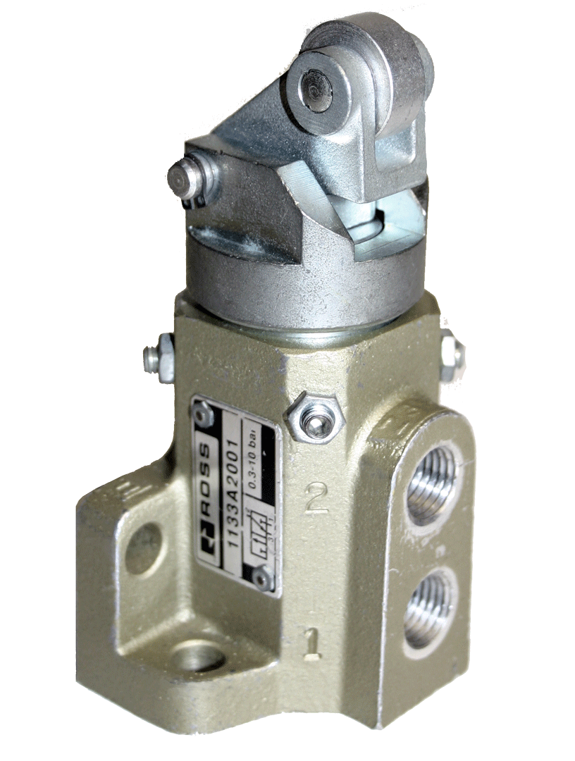
- 2-Direction Cam Roller for Bidirectional Sensing - The 2-direction cam roller variant (models 1133A2001 for 3/2, 1131A2001 for 2/2) actuates when the cam contacts the roller from either approach direction, providing end-of-stroke detection and position confirmation for reciprocating machine elements in both forward and return strokes.
- 1-Direction Cam Roller for Unidirectional Sensing - The 1-direction cam roller variant (models 1133A2002 for 3/2, 1131A2002 for 2/2) actuates only on contact from the designed cam approach direction. On contact from the opposite direction, the roller pivots away without actuating the valve, allowing the machine element to reset or pass without generating an unintended signal.
- Plunger Actuator for Direct Contact Sensing - The plunger variants (models 1133A2003 for 3/2, 1131A2003 for 2/2) use a direct-contact actuator without a roller, providing a compact footprint and straightforward direct-thrust actuation for applications where cam contact angle and roller wear are secondary considerations.
- Compact Physical Dimensions - The 11 Series cam and plunger valve body measures 1.82 inches (46 mm) by 2.76 inches (70 mm) wide, with height depending on actuator type: plunger approximately 3.27 to 3.38 inches (83 to 86 mm), 2-direction cam roller approximately 4.37 inches (111 mm), and 1-direction cam roller approximately 4.50 inches (114 mm).
- Defined Cam Travel Specifications - The 2-direction cam roller travel range is 0.07 to 0.25 inches (1.8 to 6.4 mm). The 1-direction cam roller travel range is 0.10 to 0.29 inches (2.5 to 7.4 mm). The plunger travel range is 0.05 to 0.10 inches (1.3 to 2.5 mm). These specifications define the valid actuation zone for cam and actuator profile design.
- NPT and G Thread Options - All models are available with NPT threads as standard. G (BSPP) threaded variants are available by adding a D prefix to any model number (e.g., D1133A2001 for G-threaded 3/2 2-direction cam roller).
- Remote Pilot Service Compatible - The Series is specifically described as suited to serve as remote pilots to pass operating signals to other pressure-actuated valves. The Cv 0.5 flow capacity is matched to pilot signal requirements for downstream directional control valves in common pneumatic circuit architectures.
Technical Specifications
General Specifications
| Parameter | Specification |
| Series | 11 |
| Valve Functions | 2/2 Normally Closed; 3/2 Normally Closed |
| Construction | Poppet |
| Actuator Types | 2-Direction Cam Roller; 1-Direction Cam Roller; Plunger |
| Return | Spring return (all variants) |
| Port Size | 1/4" NPT or G |
| Cv (all variants) | 0.5 |
| Operating Pressure | 5 to 150 psig (0.3 to 10 bar) |
| Ambient Temperature | 10 to 175F (-23 to 80C) |
| Media Temperature | 10 to 175F (-23 to 80C) |
| Flow Media | Filtered air |
| Valve Body Material | Cast aluminum |
| Mounting | Side and bottom mounting flanges |
| Thread Types | NPT standard; G (BSPP) by D prefix |
| Body Length | 1.82 in (46 mm) |
| Body Width | 2.76 in (70 mm) |
| Height - 2-Direction Cam Roller | 4.37 in (111 mm) |
| Height - 1-Direction Cam Roller | 4.50 in (114 mm) |
| Height - Plunger | approximately 3.27 to 3.38 in (83 to 86 mm) |
| Weight (all variants) | 1.0 lb (0.5 kg) |
| Cam Roller Travel (2-Direction) | 0.07 to 0.25 in (1.8 to 6.4 mm) |
| Cam Roller Travel (1-Direction) | 0.10 to 0.29 in (2.5 to 7.4 mm) |
| Plunger Travel | 0.05 to 0.10 in (1.3 to 2.5 mm) |
Temperature Ratings
The Series operates across the -10F to 175F (-23C to 80C) range for both ambient and media conditions. This is a wider range than the 12 Series spool valves (40F minimum), making the series suitable for cold-environment automation applications.
| Configuration | Ambient Temperature | Media Temperature |
| 11 Series Cam and Plunger Valves (all actuator types) | 10 to 175F (-23 to 80C) | 10 to 175F (-23 to 80C) |
Important: For media temperatures below 40F (4C), supply air must be free of water vapor to prevent ice formation on poppet seating surfaces. For temperatures below -10F (-23C), consult ROSS Controls for application-specific guidance.
Flow Performance Data
All Series models share Cv 0.5 and 1.0 lb (0.5 kg) weight regardless of actuator type. Differences between models are actuator geometry and directional sensitivity, not flow performance. Actuation force varies by model and operating pressure; typical actuation force range is 7 to 12 lbs for Series 11 mechanical valves.
| Valve Type | Port Size | Model (NPT) | Model (G) | Cv | Weight lb (kg) |
| 3/2 NC 2-Direction Cam Roller | 1/4" | 1133A2001 | D1133A2001 | 0.5 | 1.0 (0.5) |
| 2/2 NC 2-Direction Cam Roller | 1/4" | 1131A2001 | D1131A2001 | 0.5 | 1.0 (0.5) |
| 3/2 NC 1-Direction Cam Roller | 1/4" | 1133A2002 | D1133A2002 | 0.5 | 1.0 (0.5) |
| 2/2 NC 1-Direction Cam Roller | 1/4" | 1131A2002 | D1131A2002 | 0.5 | 1.0 (0.5) |
| 3/2 NC Plunger | 1/4" | 1133A2003 | D1133A2003 | 0.5 | 1.0 (0.5) |
| 2/2 NC Plunger | 1/4" | 1131A2003 | D1131A2003 | 0.5 | 1.0 (0.5) |
Certifications & Compliance
| Certification/Standard | Detail |
| Thread Standards | NPT standard on all models. G (BSPP, ISO 228-1) available by adding D prefix to model number (e.g., D1133A2001 for 3/2 2-direction cam roller with G ports). |
| Temperature Verification | Rated -10F to 175F (-23C to 80C) for both ambient and media conditions across all Series actuator types. |
| Mounting Compatibility | Side and bottom mounting flanges are compatible with the standard 11 Series mounting pattern shared by 11 Series palm button (256 Series) and 11 Series toggle lever (258 Series) valves. |
| CAD Models | 2D and 3D CAD models available for download in multiple formats at rosscontrols.com for all Series variants. |
Typical Applications & Industries
Automated Machine Sequencing and Position Detection
- End-of-stroke detection on pneumatic cylinders and linear actuators where the cam roller valve is mounted on the machine frame and a cam attached to the cylinder rod or actuating element contacts the roller at the desired stroke position.
- Sequential control circuits where the series valve generates the pilot signal that initiates the next step in a multi-step automation sequence after mechanical confirmation that the previous step is complete.
- Bidirectional end-of-stroke detection using 2-direction cam roller variants to confirm both the extended and retracted positions of a cylinder from a single valve mounted between the two stroke extremes.
- Rotary indexing table position confirmation where the cam on the index table contacts the cam roller valve at each dwell position to generate a pilot signal confirming correct positioning before the next machine operation begins.
Safety Interlocks and Guard Confirmation
- Machine guard door closed confirmation where a cam on the guard door contacts the plunger or cam roller valve when the guard is fully closed, generating the permissive pilot signal that allows the machine cycle to initiate.
- Two-hand control circuit interlocks where the plunger valve confirms physical contact with a machine element before the pneumatic circuit can initiate a potentially hazardous operation.
- Fixture engagement confirmation in machining centers and assembly automation where a cam attached to the fixture clamping mechanism contacts the cam roller at full clamp position, confirming proper workpiece clamping before the machining cycle initiates.
- Safety barrier and gate monitoring in automated cells where 2-direction cam roller valves detect both opening and closing of access barriers to generate interlocking pilot signals for cell entry monitoring.
Remote Pilot Signal Generation
- Mechanical pilot signal sources for larger solenoid or air-pilot directional control valves in circuits where a machine element's position must trigger a downstream valve without relying on electrical sensors or PLC control.
- Cascade circuit pilot signals in multi-cylinder pneumatic automation where the output stroke of one cylinder contacts a cam roller valve to pilot the shift of the next valve in the sequence.
- Mechanical override and backup systems for electrically controlled automation where the cam valve provides a hardwired mechanical backup circuit that operates independently of the electronic control system during power or PLC failure.
Manufacturing and Assembly Automation
- Part presence and position verification in assembly fixtures where a spring-loaded plunger valve contacts the workpiece surface at a specific location to confirm part presence and correct positioning before the assembly operation proceeds.
- Conveyor and transfer system indexing control where cam rollers mounted on the conveyor frame are contacted by carrier elements to initiate index cylinder extension and retraction at each conveyor station.
- Metal stamping and forming die protection circuits where a cam valve monitors ram position and prevents die closure if a foreign object is detected in the die space, using a mechanical signal that is immune to electrical interference.
- Plastics processing and injection molding machine auxiliary circuits where cam roller valves confirm mold closure, ejector pin retraction, and robot part removal before the next injection cycle initiates.
Ordering and Model Number Configuration
The Series uses the 11 Series model number structure. The function (2/2 or 3/2) and actuator type (2-direction cam roller, 1-direction cam roller, or plunger) are encoded in the model number. All models are 1/4 inch NPT as standard.
|
11 Series Cam and Plunger Valve Model Numbers:
1131A2001 2/2 NC, 2-Direction Cam Roller, 1/4" NPT 1131A2002 2/2 NC, 1-Direction Cam Roller, 1/4" NPT 1131A2003 2/2 NC, Plunger, 1/4" NPT 1133A2001 3/2 NC, 2-Direction Cam Roller, 1/4" NPT 1133A2002 3/2 NC, 1-Direction Cam Roller, 1/4" NPT 1133A2003 3/2 NC, Plunger, 1/4" NPT
Model number key: 11 = 11 Series body 31 = 2-way (2/2); 33 = 3-way (3/2) A = Revision level 2001 = 2-direction cam roller (NPT) 2002 = 1-direction cam roller (NPT) 2003 = Plunger (NPT)
For G (BSPP) threads: add 'D' prefix. D1133A2001 = 3/2 NC 2-direction cam roller, G threads. D1131A2003 = 2/2 NC plunger, G threads. |
Standard models ship with NPT threads. For G (BSPP) threads, add D prefix to the model number.
All six standard models share Cv 0.5, 1/4 inch port size, and 1.0 lb (0.5 kg) weight. The differences are function (2/2 or 3/2) and actuator direction (2-direction roller, 1-direction roller, or plunger).
Select 3/2 (1133A series) when the valve must provide integral exhaust for a small actuator or pilot device. Select 2/2 (1131A series) for simple on/off flow switching where exhaust routing is handled elsewhere in the circuit.
Select 2-direction cam roller (suffix 2001) for bidirectional cam contact sensing. Select 1-direction cam roller (suffix 2002) when cam contact must actuate the valve in only one travel direction. Select plunger (suffix 2003) for direct-contact actuation without roller mechanism.
Accessories
Exhaust Silencers
Aluminum exhaust silencers for 1/4 inch exhaust ports on 3/2 cam and plunger valves to reduce pilot circuit exhaust noise in high-cycle automation environments.
| Port Size | Thread | Avg Cv | Model (NPT) | Model (G) |
| 1/4" | Male | 2.1 | 5500A2003 | D5500A2003 |
Warning: Exhaust silencers must not restrict exhaust flow. In high-cycle cam valve applications, silencer contamination from cumulative exhaust cycles can build up and create back pressure that delays poppet reset and slows pilot signal release.
Related Products & Accessories
- Palm and Push Button Valves (256 Series) - 11 and 12 Series manual pushbutton and palm button valves sharing the same 11 Series body and mounting pattern as the series cam valves. https://www.rosscontrols.com/en/series/256-palm-push-button-valves
- Lever Valves (258 Series) - 11 Series toggle lever valves using the same 11 Series body, for manual operation at the same valve mounting locations. https://www.rosscontrols.com/en/series/258-lever-valves
- Pedal and Treadle Valves (259 Series) - 36 and RM Series foot-operated poppet valves for hands-free operator-initiated circuit control. https://www.rosscontrols.com/en/series/259-pedal-treadle-valves
- Pendant Valves (255 Series) - Manual pendant control valves for material handling and overhead crane applications. https://www.rosscontrols.com/en/series/255-pendant-valves
- Exhaust Silencers - Aluminum silencers for 1/4 inch exhaust ports on cam and plunger valves in high-cycle automation installations. https://www.rosscontrols.com/en/series/90-silencers
- Lockout Valves L-O-X - Energy isolation devices for OSHA-compliant lockout/tagout of pneumatic automation circuits during cam valve maintenance. https://www.rosscontrols.com/en/series/1287-lockout-valves-15-series
Frequently Asked Questions (FAQ)
Q: What is the difference between a 2-direction and 1-direction cam roller valve?
A: The 2-direction cam roller valve actuates when the cam contacts the roller from either the approach or the departure direction of cam travel. This is used when both stroke directions need to trigger the valve, such as both extension and retraction of a cylinder. The 1-direction cam roller actuates only from one cam approach direction; contact from the opposite direction causes the roller to pivot away without actuating the valve poppet. This is used when only one stroke direction should generate a signal, and the cam must pass back without re-triggering the valve during the return stroke.
Q: Why choose a cam roller valve over an electronic proximity switch with a solenoid valve?
A: Cam roller valves eliminate the transducer chain: they combine position detection and air circuit switching in a single device with no electrical wiring, no PLC input card, no solenoid driver, and no electrical power requirement. This reduces component count, installation wiring, failure modes, and electrical design complexity in pneumatic-primary automation systems. Cam valves are also immune to electromagnetic interference and function during power outages. The tradeoff is that cam valves require physical contact and mechanical cam profile design, whereas proximity switches can sense without contact.
Q: What cam profile specifications should I use for cam roller valve design?
A: Recommended cam approach angle is 30 to 45 degrees to minimize impact force on the roller and valve stem during initial contact. The cam must provide sufficient dwell engagement to travel through the full valid actuation stroke zone: 0.07 to 0.25 inches (1.8 to 6.4 mm) for the 2-direction roller, and 0.10 to 0.29 inches (2.5 to 7.4 mm) for the 1-direction roller. The cam surface in contact with the roller should be hardened tool steel or case-hardened steel to minimize wear over millions of actuation cycles. Design the cam to over-travel beyond the minimum valid actuation stroke to compensate for normal machine tolerance accumulation and wear.
Q: What is the plunger travel specification and what actuator design considerations apply?
A: The plunger travel range is 0.05 to 0.10 inches (1.3 to 2.5 mm). The actuating surface must provide sufficient force throughout this travel range to overcome the poppet spring force plus the pneumatic back-pressure force from the supply pressure at the inlet. Because the plunger travel is shorter than the cam roller travel, plunger applications require more precise machine element positioning to ensure reliable actuation within the defined valid travel zone.
Q: Can the series valves be mounted in any orientation?
A: Yes. Series 11 mechanical valves can be mounted in any orientation using the side or bottom mounting flanges without affecting valve performance. Mounting orientation does not affect the poppet sealing mechanism or the spring return force. Select the mounting orientation that places the cam roller or plunger in the most accessible position relative to the actuating machine element.
Q: What actuation force is required to operate the cam and plunger valves?
A: Typical actuation force range for Series 11 mechanical valves is 7 to 12 lbs, depending on operating pressure and specific model. The cam or machine element must provide sufficient contact force to overcome the poppet spring return force plus the differential pneumatic force from inlet pressure. Higher supply pressures require higher actuation forces. Consult the ROSS catalog or contact ROSS for specific actuation force data for a given operating pressure.
Q: Are the series cam valves suitable for safety interlock applications?
A: The Series cam and plunger valves provide mechanically-actuated pneumatic signals suitable for interlocking applications in pneumatic-primary control circuits. For safety-rated interlock circuits meeting specific PLr (performance level) or SIL requirements per ISO 13849 or IEC 62061, consult ROSS about the appropriate safety valve products. The Series cam valves are not TUV safety-certified and should not be used as the sole safety element in rated safety function circuits without appropriate risk assessment.
Q: How do I select between 2/2 and 3/2 function for a cam valve pilot circuit?
A: Use the 2/2 (1131A series) when the cam valve must provide a simple on/off flow signal and exhaust of the downstream pilot volume is handled by a separate exhaust path in the circuit. Use the 3/2 (1133A series) when the cam valve must also actively vent the downstream pilot volume when the cam disengages, providing faster downstream valve reset and reducing the pilot signal dwell time after cam release. The 3/2 function is more common in sequential control circuits where fast signal release is as important as fast signal generation.
Q: What maintenance is required for cam and plunger valves in high-cycle applications?
A: In high-cycle automation applications (hundreds of thousands to millions of cycles per year), inspect cam roller wear, roller bearing condition, and roller pivot pin wear at scheduled maintenance intervals. Replace worn rollers and bearings to maintain consistent actuation force and contact geometry. Inspect the plunger tip on plunger variants for wear and deformation. Service kits with replacement poppet seals, springs, and actuator components are available from ROSS for field refurbishment without complete valve replacement.
Q: Can the series valves be used for fluid media other than compressed air?
A: No. All Series cam and plunger valves are designed for filtered compressed air service only. They are not rated for hydraulic fluids, water, process gases, or other liquid or gaseous media. Using non-air media will degrade seals and internal components.
Q: What is the recommended minimum filtration for the supply air to cam and plunger valves?
A: ROSS recommends filtered compressed air for all Series valves. In automation environments, the valve may be exposed to coolant mist, metal dust, and airborne contamination, making upstream filtration critical. A 5-micron or finer coalescing filter upstream of the cam valve supply is recommended to protect the poppet sealing surfaces and extend service life between seal replacements.
Q: Can I use the same 11 Series mounting footprint for cam valves and manual valves in different production states?
A: Yes. The 11 Series body and mounting flange pattern are shared across the cam roller, plunger, palm button (256 Series), and toggle lever (258 Series) product variants. This allows a machine to be designed with a common mounting interface that can accept either a mechanical cam valve for automated production or a manual palm button or toggle lever for manual operation during commissioning, tooling change, or maintenance, without modifying the mounting structure.
Installation & Maintenance Guidelines
- Mount the cam or plunger valve using the side or bottom mounting flanges with fasteners appropriate for the mounting surface and the expected actuation force. Ensure the valve body is secure and cannot shift under cam contact force during high-speed machine operation.
- Position the valve so that the cam roller or plunger is in the travel path of the actuating machine element at the precise position where the pilot signal should be generated. Use a dial indicator or measurement method to verify the contact position relative to machine reference datums.
- For cam roller valves, design the cam profile with an approach angle of 30 to 45 degrees to reduce impact loading on the roller at contact initiation. Ensure the cam provides sufficient dwell length to keep the roller within the valid actuation zone (0.07 to 0.25 inch for 2-direction, 0.10 to 0.29 inch for 1-direction) throughout the machine dwell period.
- For plunger valves, ensure the actuating surface makes contact perpendicular to the plunger axis. Side-loading of the plunger can increase seal wear and reduce reliable actuation. The actuating surface should travel through the full plunger valid stroke range of 0.05 to 0.10 inches.
- Connect port 1 to the filtered compressed air supply and port 2 to the downstream actuator or pilot valve. For 3/2 models, connect port 3 to atmosphere through a silencer or to atmosphere directly, routed away from machine elements, operators, and sensitive equipment.
- After installation, manually actuate the cam roller or plunger by hand (with the machine depressurized) to verify that the valve shifts and that port 2 pressure is present at the outlet. Release the actuator and verify that the valve spring-returns and port 2 pressure drops. This confirms correct port assignment and valve function before live machine operation.
- Verify that the cam or machine element contacts the roller or plunger at the correct machine position by jogging the machine through its stroke at reduced speed and confirming that the pilot signal appears and disappears at the intended positions on the machine controller or pressure gauge.
- Supply filtered air through a 5-micron coalescing filter upstream of the cam valve supply. Automation environments with cutting fluid mist, grinding dust, or scale particles require filtration to prevent contaminants from reaching the poppet seat and causing leakage or sticking.
- Do not exceed 150 psig (10 bar) at port 1. Verify the upstream regulator setting before connecting the valve to the live compressed air system.
- For cam roller valves in high-speed applications, verify that the machine element speed at the cam contact point does not produce impact forces that exceed the cam roller design load. Excessive contact speed can cause roller bearing damage and accelerated valve wear. If necessary, reduce approach speed or redesign the cam dwell length.
- Protect the cam roller or plunger actuator from direct coolant spray and chip impingement with a shield or cover where possible. While the poppet construction tolerates contamination better than spool valves, minimizing actuator exposure to coolant and chips extends roller bearing and seal life.
- Establish a periodic inspection schedule for cam roller valves in high-cycle production applications. Check roller condition, cam surface wear, and mounting security at each scheduled machine maintenance interval. In continuous production applications cycling at high rates, consider reducing inspection intervals during the first few months of operation to establish an appropriate wear-based service interval.
Warranty & Global Support
ROSS Controls provides a one-year warranty on all Series cam and plunger valves, covering defects in material and workmanship from the date of purchase.
Technical support and automation application assistance are available through ROSS Controls USA at (800) 438-7677 or through ROSS global offices in Canada, Brazil, Germany, France, United Kingdom, India, China, and Japan.
Service kits with replacement seals, poppets, springs, and actuator components are available for field refurbishment of all Series cam and plunger valve variants.
For dimensional drawings including critical cam contact point dimensions, CAD models, and complete technical specifications, visit the ROSS Controls product page at rosscontrols.com or contact your authorized ROSS distributor.
Download Catalog: https://www.rosscontrols.com/en/documents/3885
Download Documents
Cam & Plunger Valves
