Pedal & Treadle Valves 36 & RM Series
- Reliable poppet design
- 3/2 and 4/2 normally closed Pedal & Treadle Valves
- 5/2 Foot Pedal Valves are convertible to a 3-way function
- Ruggedly-built for extended life
Pedal & Treadle Valves 36 & RM Series Product Overview
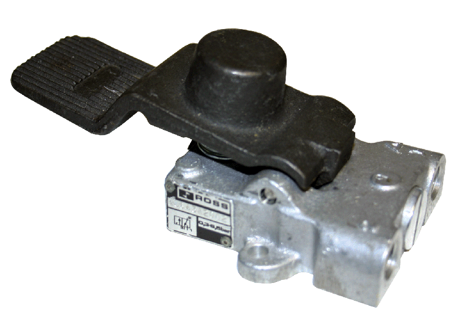
ROSS foot operated valves are designed to provide foot actuation in a valve especially suited for remote pilot service. Foot operated poppet valves for small, fast, single or double-acting cylinder or pneumatic actuator applications on machines, jigs, fixtures, etc.
Please refer to the side and below for links to easily navigate and download ROSS Controls Pedal & Treadle Valves 36 & RM Series catalogs, installation instructions, and technical data. Additionally, you have the option to filter through all available options to Pedal & Treadle Valves 36 & RM Series variant that meets your requirements.
loading...
loading...
Product Overview
The ROSS Controls encompasses two families of foot-operated pneumatic directional control valves: the 36 Series Pedal and Treadle valves for general-purpose foot-actuated circuit control, and the RM Series Foot Pedal with Guard designed to meet OSHA 1910.217 requirements for mechanical power press applications. Both families provide hands-free pneumatic control, freeing both operator hands for workpiece handling, part placement, and tooling operations.
The 36 Series Pedal and Treadle valves use the same poppet valve internals and body platform as the 36 Series Lever valves in the 258 Series, providing 3/2 and 4/2 functions at 1/4 inch NPT or G ports with Cv 1.2. The pedal variant uses a spring-return foot pedal for momentary actuation, while the treadle variant uses a detented foot pedal that maintains its shifted position after the operator's foot is removed. Both are line-mounted (inline) poppet valves rated at 5 to 150 psig operating pressure, with the 36 Series rated at 5 to 125 psig specifically for pedal applications.
The RM Series Foot Pedal with Guard is specifically engineered for applications governed by OSHA 1910.217 machine safety requirements, notably mechanical power press operations. The guard housing prevents accidental foot actuation by requiring the operator to deliberately insert their foot under the guard before pressing the pedal. The 5/2 (five-port, two-position) valve function is convertible to a 3-way configuration in the field. Available in non-locking and locking foot pedal configurations, these valves provide the safety-critical foot control function with both standard actuation and maintained-position locking for applications requiring sustained pedal engagement.
For design engineers specifying foot-operated controls in manufacturing environments, the series provides foot actuation options from general-duty production operations to safety-regulated press control in a poppet design that withstands floor-level contamination, chip and coolant exposure, and the mechanical demands of repetitive foot actuation over extended production runs.
Key Engineering Features
- Two Distinct Pedal Valve Families - The 36 Series provides general-purpose 3/2 and 4/2 foot-operated directional control in pedal (spring return) and treadle (detented) configurations. The RM Series provides OSHA 1910.217-compliant 5/2 foot control with a guarded housing designed to prevent accidental actuation.
- Poppet Construction for Floor-Level Durability - All Series valves use poppet valve internals that resist chip, coolant, and dirt contamination at floor level where pedal valves operate. The poppet seal seats positively under spring force, preventing leakage even when contaminated fluid temporarily contacts the valve body.
- OSHA 1910.217 Compliance (RM Series) - The RM Series Foot Pedal with Guard is specifically cited for compliance with OSHA 1910.217, the mechanical power press standard requiring guarded foot pedal controls to prevent accidental press actuation. Both locking and non-locking foot pedal variants are available.
- 5/2 Function Convertible to 3-Way (RM Series) - The RM Series 5/2 valve is field-convertible to a 3-way function by plugging one of the outlet ports, providing flexibility for applications requiring either 5-port or 3-port circuit configuration from the same valve model without ordering a different part number.
- Detented Treadle for Maintained-Position Control - The 36 Series treadle variant provides a detented foot pedal that holds the shifted position after the operator removes their foot, enabling maintained directional selection for extended work cycles where continuous foot contact is impractical or creates operator fatigue.
- Locking and Non-Locking RM Series Options - The RM Series is available in a non-locking (RM4F210-08G) and locking foot pedal (RM4F210-08LG) configuration. The locking variant engages a mechanical lock to hold the pedal in the actuated position for applications requiring sustained actuation without continuous foot force.
- Broad Operating Pressure Range - The 36 Series pedal and treadle valves operate at 5 to 125 psig (0.3 to 8.5 bar) and must not be used on clutch/brake circuits for mechanical power presses. The RM Series foot pedal operates at 0 to 120 psig (0 to 8.2 bar).
- Inline Line Mounting - Both the 36 Series and RM Series use inline line mounting, connecting directly into the pneumatic supply line without requiring separate manifolds or sub-base mounting hardware.
- NPT Threads Standard - Standard models ship with NPT threads. G (BSPP) threaded variants are available on 36 Series models by adding a D prefix (e.g., D3643A2001). RM Series models are available in NPT only.
- Ruggedly Built for Extended Production Life - The cast aluminum valve body and stainless steel internal components resist the mechanical wear, corrosion, and contamination exposure encountered at floor level in metal cutting, stamping, assembly, and general manufacturing environments.
Technical Specifications
General Specifications
| Parameter | Specification |
| Valve Families | 36 Series Pedal (Spring Return); 36 Series Treadle (Detented); RM Series Foot Pedal with Guard |
| 36 Series Functions | 3/2 Normally Closed; 4/2 Normally Open |
| RM Series Function | 5/2 (convertible to 3-way) |
| Construction | Poppet (all variants) |
| Mounting | Inline line mounting (all variants) |
| Port Size - 36 Series | 1/4" NPT or G |
| Port Size - RM Series | 1/4" NPT |
| Maximum Cv - 36 Series | 1.2 |
| Maximum Cv - RM Series | 0.5 |
| Operating Pressure - 36 Series | 5 to 125 psig (0.3 to 8.5 bar) |
| Operating Pressure - RM Series | 0 to 120 psig (0 to 8.2 bar) |
| Ambient Temperature - 36 Series (catalog spec) | 40 to 175F (4 to 80C) |
| Ambient Temperature - 36 Series (variant data) | 30 to 175F (-34 to 80C) per product variant data |
| Media Temperature - 36 Series | 30 to 175F (-34 to 80C) |
| Ambient Temperature - RM Series | 23 to 140F (-5 to 60C) |
| Media Temperature - RM Series | 23 to 140F (-5 to 60C) |
| Flow Media | Filtered air |
| Valve Body Material | Cast aluminum |
| Thread Types | NPT standard (all); G (BSPP) for 36 Series by D prefix |
Temperature Ratings
The 36 Series product variant data shows an ambient and media temperature range of -30F to 175F, which is broader than the 40F to 175F range listed in the general catalog. The RM Series foot pedal is rated to a narrower temperature range of 23F to 140F. Confirm the applicable temperature range with ROSS for the specific product variant required.
| Configuration | Ambient Temperature | Media Temperature |
| 36 Series Pedal and Treadle (general catalog rating) | 40 to 175F (4 to 80C) | 40 to 175F (4 to 80C) |
| 36 Series Pedal and Treadle (product variant data) | 30 to 175F (-34 to 80C) | 30 to 175F (-34 to 80C) |
| RM Series Foot Pedal with Guard | 23 to 140F (-5 to 60C) | 23 to 140F (-5 to 60C) |
Important: For media temperatures below 40F (4C), supply air must be free of water vapor to prevent ice formation inside the valve. The RM Series is not rated for operation below 23F (-5C).
Flow Performance Data
Cv values are average flow coefficients at rated conditions. Response time formula for 36 Series: Response Time (ms) = M + (F x V) where M is taken as zero for manual actuation and V is downstream volume in cubic inches. F values: F(1-2) = 1.66 fill; F(2-3) = 1.43 exhaust.
| Valve Type | Port Size | Model | Cv | F 1-2 | F 2-3 | Weight lb (kg) |
| 3/2 Pedal, Spring Return | 1/4" | 3643A2002 | 1.2 | 1.66 | 1.43 | 1.3 (0.6) |
| 3/2 Treadle, Detented | 1/4" | 3643A2001 | 1.2 | 1.66 | 1.43 | 1.3 (0.6) |
| 4/2 Pedal, Spring Return | 1/4" | 3646A2002 | 1.2 | 2.8 (1.3) | ||
| 4/2 Treadle, Detented | 1/4" | 3646A2001 | 1.2 | 2.8 (1.3) | ||
| 5/2 Non-Locking Foot Pedal (RM Series) | 1/4" | RM4F210-08G | 0.5 | N/A | N/A | 2.1 (0.9) |
| 5/2 Locking Foot Pedal (RM Series) | 1/4" | RM4F210-08LG | 0.5 | N/A | N/A | 2.1 (0.9) |
Certifications & Compliance
| Certification/Standard | Detail |
| OSHA 1910.217 (RM Series) | The RM Series Foot Pedal with Guard meets OSHA 1910.217 requirements for foot-operated controls on mechanical power presses, featuring a guard housing that prevents accidental actuation. |
| Thread Standards | NPT standard on all models. G (BSPP, ISO 228-1) available on 36 Series by adding D prefix (e.g., D3643A2001). RM Series available in NPT only. |
| Application Restriction (36 Series) | ROSS explicitly states that 36 Series pedal and treadle valves are NOT for use on clutch/brake circuits of mechanical power presses. Use the RM Series for press applications. |
| CAD Models | 2D and 3D CAD models available for download at rosscontrols.com for all Series variants. |
Typical Applications & Industries
Hands-Free Machine Control
- Fixture clamping and unclamping in manual assembly operations where both operator hands must be free to position the workpiece during loading and unloading, with foot pedal actuation initiating clamp cylinder extension after the part is placed.
- Press and punch tooling control on non-mechanical power presses where the operator uses both hands to position sheet metal blanks and uses the foot pedal to initiate the pneumatic press stroke, keeping hands clear of the tooling zone.
- Welding fixture control where the operator clamps the workpiece with a foot pedal, then uses both hands to guide the welding torch or position filler wire during the weld operation.
- Spray and dispensing system actuation at assembly workstations where the operator uses the foot pedal to trigger adhesive dispensers, sealant guns, or paint spray systems while using both hands to guide the applicator nozzle.
Jig, Fixture, and Automation Applications
- Pneumatic cylinder indexing on assembly jigs where the foot pedal advances the index mechanism between work positions, allowing the operator to perform assembly steps at each station with both hands.
- Air ejectors and part ejection systems at machining centers and presses where the foot pedal initiates workpiece ejection after the machining cycle, freeing operator hands for receiving the ejected part.
- Vacuum cup release and pick-and-place systems where the treadle detented configuration allows the operator to set the vacuum state and hold it during part transport, then press the pedal again to release the part at the destination.
- Pneumatic test stand control where the operator uses a foot pedal to pressurize test fixtures while using both hands to connect and disconnect test couplings, check instruments, and record results.
Mechanical Power Press Control (RM Series)
- Mechanical power press foot control meeting OSHA 1910.217 requirements, where the guarded foot pedal housing prevents accidental press actuation from tools, debris, or incidental foot contact at the press station.
- Clutch and brake pilot signal generation for press-integrated safety control systems where the RM Series foot pedal initiates the press cycle while the 5/2 function provides both forward and return pilot signals in a single valve.
- Locking foot pedal applications where sustained pedal engagement is required throughout a press cycle without the operator maintaining continuous foot pressure, using the locking RM4F210-08LG variant.
General Manufacturing and Process
- Rotary actuator and turntable control at assembly workstations where foot pedal control allows the operator to advance index positions while using both hands for part assembly tasks.
- Pneumatic transfer and lift systems in material handling where a floor-mounted treadle valve controls lifts, transfers, or elevators, allowing hands-free actuation for operators handling materials.
- Packaging and labeling equipment where the operator uses foot pedal control to sequence packaging operations while guiding products with both hands.
Ordering and Model Number Configuration
The Series includes 36 Series pedal and treadle models and RM Series foot pedal with guard models. Model numbers encode the series, function, port size, and pedal type.
|
36 Series Pedal and Treadle Models:
3643A2001 3/2 Treadle, Detented, 1/4" NPT, Cv 1.2 3643A2002 3/2 Pedal, Spring Return, 1/4" NPT, Cv 1.2 3646A2001 4/2 Treadle, Detented, 1/4" NPT, Cv 1.2 3646A2002 4/2 Pedal, Spring Return, 1/4" NPT, Cv 1.2
Model number key: 36 = Series, 4 = 4-way or 3 = 3-way 3 or 6 = body size/port indicator, A = revision 2001 = NPT Treadle (detented), 2002 = NPT Pedal (spring return)
RM Series Foot Pedal with Guard Models:
RM4F210-08G 5/2 Foot Pedal, Non-Locking, 1/4" NPT, Cv 0.5 RM4F210-08LG 5/2 Foot Pedal, Locking, 1/4" NPT, Cv 0.5
For G (BSPP) threads on 36 Series: add 'D' prefix. D3643A2001 = 3/2 Treadle Detented with G threads. RM Series is NPT only; no G-thread variant available. |
36 Series standard models ship with NPT threads. For G (BSPP) threads on 36 Series, add D prefix to the model number.
RM Series foot pedal with guard models are available in NPT thread only. No G-thread variant is available.
36 Series pedal and treadle valves must NOT be used on clutch/brake circuits of mechanical power presses. Use the RM Series for press applications.
The RM Series 5/2 valve is field-convertible to a 3-way function by plugging one of the two outlet ports. This provides flexibility without requiring a separate model number for 3-way applications.
Accessories
Exhaust Silencers
Aluminum exhaust silencers for 1/4 inch exhaust ports on 36 Series pedal and treadle valves. Silencer Cv must be equal to or greater than the valve exhaust Cv of 1.2.
| Port Size | Thread | Avg Cv | Model (NPT) | Model (G) |
| 1/4" | Male | 2.1 | 5500A2003 | D5500A2003 |
Warning: Exhaust silencers must not restrict exhaust flow below the valve exhaust capacity. A contaminated silencer on a foot pedal valve creates back pressure that slows cylinder return speed and can cause the pedal to feel stiff or resist spring return.
ROSS L-O-X Energy Isolation Devices
ROSS L-O-X lockout valves provide OSHA-compliant lockout/tagout energy isolation for pneumatic systems incorporating foot pedal and treadle valves during maintenance. Install upstream of the foot valve for proper energy isolation.
Related Products & Accessories
- Lever Valves (258 Series) - 11, 31, and 36 Series lever valves sharing the same 36 Series body platform as the series pedal valves. https://www.rosscontrols.com/en/series/258-lever-valves
- Palm and Push Button Valves (256 Series) - 11 and 12 Series manual pushbutton and palm button valves for hand-operated machine controls at the same workstations. https://www.rosscontrols.com/en/series/256-palm-push-button-valves
- Cam and Plunger Valves (260 Series) - 11 Series mechanical cam roller and plunger valves for automated machine-actuated circuit control. https://www.rosscontrols.com/en/series/260-cam-plunger-valves
- Lockout Valves L-O-X - Energy isolation devices for OSHA-compliant lockout/tagout of pneumatic circuits including foot pedal systems during maintenance. https://www.rosscontrols.com/en/series/1287-lockout-valves-15-series
- Exhaust Silencers - Aluminum silencers for foot valve exhaust ports to reduce noise at floor-level operator stations. https://www.rosscontrols.com/en/series/90-silencers
Frequently Asked Questions (FAQ)
Q: What is the difference between a pedal valve and a treadle valve?
A: The 36 Series pedal valve uses a spring-return foot pedal that returns to the unactuated position when the operator removes foot pressure. The 36 Series treadle valve uses a detented foot pedal mechanism that holds the shifted position after foot pressure is removed. Use pedal (spring return) for applications requiring the valve to return to default when the operator's foot is raised. Use treadle (detented) for maintained-position applications where the operator needs to step off the pedal without changing the circuit state.
Q: When should I use the RM Series instead of the 36 Series for press applications?
A: The RM Series Foot Pedal with Guard is required for OSHA 1910.217 compliance on mechanical power presses. The 36 Series pedal and treadle valves are explicitly not rated for clutch/brake circuits on mechanical power presses. If the foot valve is used to control any portion of the press clutch, brake, or cycle initiation circuit on a mechanical power press, the RM Series with its OSHA-compliant guard housing must be used.
Q: Can the RM Series 5/2 valve be converted to a 3-way function?
A: Yes. The RM Series 5/2 valve can be field-converted to a 3-way function by plugging one of the two outlet ports using a pipe plug in the appropriate port. This allows a single RM Series model to serve both 5-port and 3-port circuit configurations without requiring a separate valve model for each application.
Q: What is the maximum operating pressure for the 36 Series pedal valve?
A: The 36 Series pedal and treadle valves are rated at 5 to 125 psig (0.3 to 8.5 bar) maximum operating pressure for pedal applications, which is lower than the 150 psig limit of the related 36 Series lever valves. This distinction applies specifically to the foot-operated pedal and treadle variants.
Q: Are the 36 Series pedal valves the same internal construction as the 36 Series lever valves in the 258 Series?
A: Yes. The 36 Series pedal and treadle valves use the same poppet valve body, internal components, and port sizes as the 36 Series lever valves in the 258 Series product line. The difference is the actuator mechanism: foot pedal or treadle instead of a hand lever. Cv ratings, port sizes, and flow characteristics are identical.
Q: What is the weight difference between the 3/2 and 4/2 pedal valves?
A: The 3/2 pedal and treadle valves (3643A2001, 3643A2002) weigh 1.3 lb (0.6 kg). The 4/2 pedal and treadle valves (3646A2001, 3646A2002) weigh 2.8 lb (1.3 kg), more than double, due to the larger four-way valve body required for the additional circuit function. Dimensional data: 3/2 treadle 3.44 x 6.0 x 1.9 in; 4/2 treadle 3.65 x 6.5 x 2.5 in.
Q: Can foot pedal valves be installed in wet or coolant-contaminated environments?
A: The cast aluminum body and poppet construction provide reasonable resistance to coolant splash and floor-level contamination. The valves are not sealed or rated for immersion or sustained exposure to coolant streams. Position the valve to minimize direct coolant impingement, and ensure that contamination cannot enter the exhaust port and reach the poppet sealing surfaces during normal production.
Q: What is the OSHA 1910.217 requirement that the RM Series addresses?
A: OSHA 1910.217 governs mechanical power presses and requires foot controls to be guarded to prevent accidental operation by a falling object, the operator's foot slipping, or any other unintended contact. The RM Series foot pedal with guard provides the guard housing required by this standard. The standard also specifies requirements for two-hand trips and light curtains for specific hazard levels; the RM Series addresses the foot control guarding requirement specifically.
Q: Are the series valves suitable for hydraulic circuits?
A: No. All Series pedal and treadle valves are rated for filtered compressed air only. They are not rated for hydraulic fluid, water, or other liquid media. Use hydraulic foot valves specifically rated for liquid media in hydraulic applications.
Q: How do I select between 3/2 and 4/2 function for my application?
A: Use the 3/2 function for single-acting cylinders (spring return) where the foot pedal extends the cylinder and releasing the pedal allows the spring to return it, or for pilot signal applications where only one pilot signal is needed. Use the 4/2 function for double-acting cylinders where the foot pedal actuates the advance stroke and the valve's opposite position connects the return cylinder port to exhaust, providing active retraction even with a spring-return pedal.
Q: Can the foot pedal valves be used as remote pilot signals for larger valves?
A: Yes. The 36 Series pedal and treadle valves with Cv 1.2 can serve as remote air pilot signal sources for larger pilot-operated directional control valves with port sizes up to 2-1/2 inch, enabling hands-free manual pilot control of high-flow circuits without requiring the foot pedal to carry the full system flow.
Q: What maintenance is required for foot pedal valves?
A: Inspect the foot pedal mechanism, spring, and pedal pivot for wear at scheduled maintenance intervals. Check that the pedal return spring operates freely and returns the pedal to the unactuated position. Inspect for contamination accumulation in the pedal guard or around the valve body that could interfere with pedal travel. Verify poppet sealing by checking for air leakage at the exhaust port in the unactuated position. Service kits with replacement seals are available from ROSS.
Installation & Maintenance Guidelines
- Mount the pedal valve in the inline orientation with port 1 connected to the compressed air supply and port 2 (and port 4 on 4/2 valves) connected to the actuator. Secure the valve to the floor or machine base using appropriate mounting hardware to prevent movement during foot actuation.
- Position the foot pedal at a height and angle that allows comfortable foot actuation without requiring the operator to shift their weight or alter their standing posture. Recommended pedal height for standing operators is approximately 2 to 4 inches above floor level.
- For RM Series foot pedal with guard installations, position the guard opening to face the operator's approach direction so that foot insertion into the guard housing requires intentional foot placement. Do not position the guard so that it is accessible from multiple directions simultaneously.
- Connect port 3 (exhaust) to atmosphere through a silencer or silencer with sufficient Cv to match the valve exhaust capacity. Route the exhaust away from the floor area to prevent contamination from the exhaust airflow blowing floor debris back into the valve body.
- Supply filtered compressed air from an upstream FRL unit. Install a 5-micron or finer filter in the supply line upstream of the foot valve. At floor level, air quality is often lower than at machine panel height due to proximity to coolant and chip sources.
- Do not exceed the maximum operating pressure for the valve variant: 125 psig (8.5 bar) for 36 Series pedal and treadle valves, and 120 psig (8.2 bar) for RM Series foot pedal with guard models.
- For treadle (detented) variants, verify that the detent mechanism engages fully in both positions before placing the machine in service. Partially engaged detents can allow the pedal to shift under vibration or foot brush contact, creating unintended circuit state changes.
- After installation, test the spring return function (for pedal variants) by depressing and releasing the pedal repeatedly. The pedal must return fully to the unactuated position on each release. Sluggish return indicates a restricted exhaust port or contamination on the poppet seat.
- For cold-weather floor-level installations, verify that the expected ambient temperature stays above the minimum operating temperature for the valve variant: 40F for 36 Series (or -30F per product variant data), and 23F for the RM Series. Cold-temperature exposure can stiffen pedal return springs and slow poppet response.
- Provide adequate guarding around the pedal valve to prevent accidental actuation from falling workpieces, tools, or materials at the workstation. This is a general manufacturing safety requirement for all foot controls, not only OSHA 1910.217 press applications.
- Route air supply and exhaust lines so they do not create tripping hazards for the operator at the pedal valve location. Use conduit, cable trays, or floor routing channels to keep pneumatic lines away from walking surfaces near pedal stations.
- Inspect pedal mechanisms, guard housings, mounting hardware, and air connections at each scheduled machine maintenance interval. Floor-level installations experience higher mechanical shock, vibration, and contamination exposure than panel-mounted valves, requiring more frequent inspection.
Warranty & Global Support
ROSS Controls provides a one-year warranty on all Series pedal and treadle valves, covering defects in material and workmanship from the date of purchase.
Technical support is available through ROSS Controls USA at (800) 438-7677 or through ROSS global offices in Canada, Brazil, Germany, France, United Kingdom, India, China, and Japan.
Service kits with replacement seals and internal components are available for field refurbishment of 36 Series and RM Series pedal valves. Provide the complete model number when requesting service parts.
For dimensional drawings, CAD models, and complete technical specifications, visit the ROSS Controls product page at rosscontrols.com or contact your authorized ROSS distributor.
Product Catalog - Foot Operated Valves: https://www.rosscontrols.com/en/documents/3882?filename=Foot_Operated_Valves_ROSS-MV-FO_EN.pdf
Installation Instructions - 31 & 36 Series: https://www.rosscontrols.com/en/documents/53?filename=ROSS_31_36_Series_Manual_Valves_Installation_Instructions_SS104.pdf
Download Documents
Pedal & Treadle Valves
