Double Valves with or w/o Pressure Switches, Ports 1/4 to 3/4 Crossflow 35 Series
- Designed to enable users to comply with current safety regulations
- Can be integrated with external monitoring systems to provide for lockout and inhibiting further machine operation until the controls system is reset
- Default to de-energized position upon fault condition
Double Valves with or w/o Pressure Switches, Ports ¼ to ¾ Crossflow 35 Series Product Overview
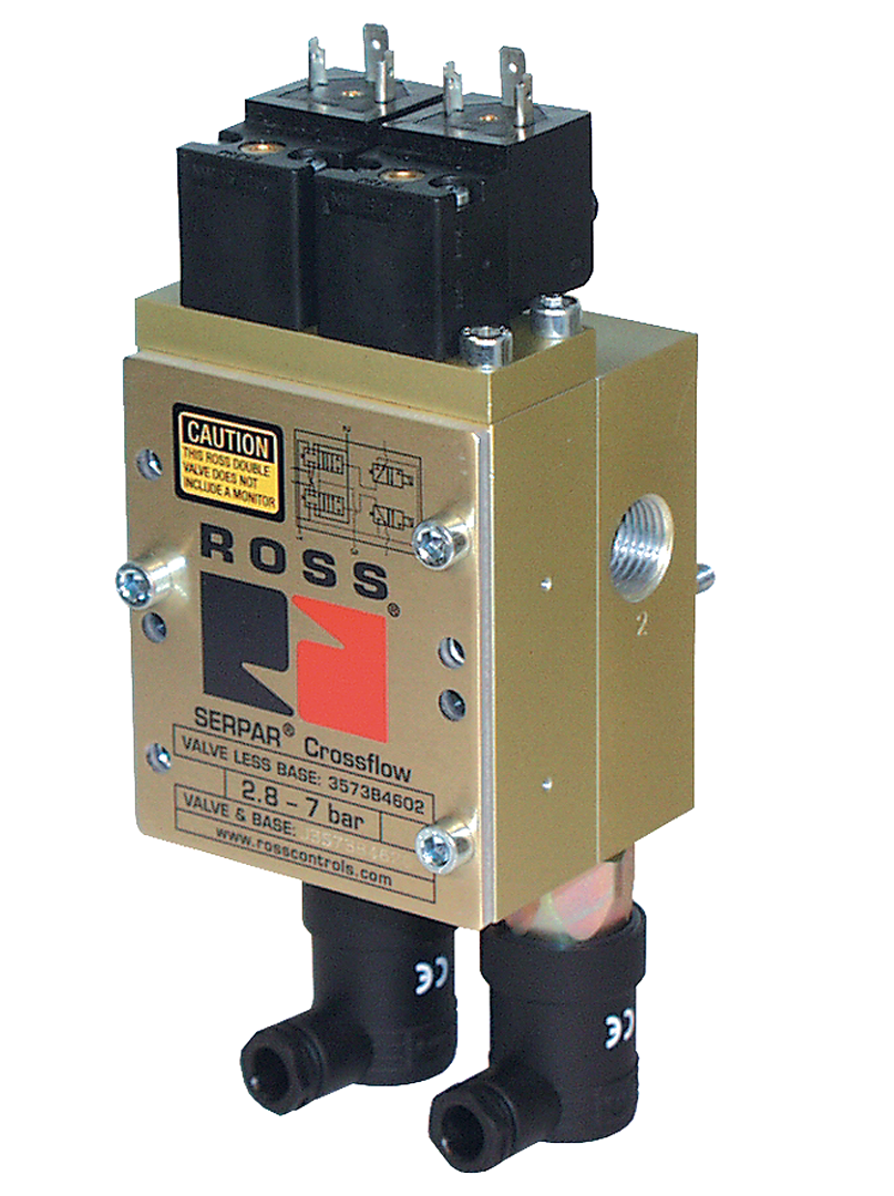
The CrossFlow double valve is designed to provide control of clutch/brake mechanisms on stamping presses, and many other critical applications such as alternative lockout systems for energy isolation, air cylinder press load-holding systems, as well as other Category -3 and -4 safety circuits.
Please refer to the side and below for links to easily navigate and Double Valves with or w/o Pressure Switches, Ports 1/4 to ¾ Crossflow 35 Series catalogs, installation instructions, and technical data. Additionally, you have the option to filter through all available options to discover the ideal Double Valves with or w/o Pressure Switches, Ports 1/4 to ¾ Crossflow 35 Series variant that meets your requirements.
loading...
loading...
Product Overview
The ROSS Controls CrossFlow 35 Series Double Valves with or without Pressure Switches for port sizes 1/4 to 3/4 in. are control-reliable double valves on Basic Sizes 1 and 2, designed for clutch/brake control on stamping presses and Category 3 and 4 safety circuits including alternative lockout systems for energy isolation and air cylinder press load-holding systems.
This series offers CrossFlow double valves both with and without pressure switches. Valves without pressure switches are available for non-press applications or as base-only valve elements in custom press safety circuit architectures. Valves with pressure switches provide feedback signals that allow the main press controls or a separate monitoring device to check the proper operation of each valve element on every cycle.
Pressure switch ports are provided on all valve bases regardless of initial switch configuration, enabling future upgrade from no-switch to two-switch configuration by adding switches without replacing the base. Basic Size 1 is base mounted with captive valve-to-base screws, and Basic Size 2 is base mounted with right or left inlet orientation.
Basic Size 1 covers 1/4 and 3/8 in. port sizes. Basic Size 2 covers 1/2 and 3/4 in. inlet/outlet with 3/4 and 1 in. exhaust options. Both sizes are base mounted with standard DIN electrical connections and meet Category 4 PL e per ISO 13849-1:2015 and SIL 3 per IEC 62061:2001.
Key Engineering Features
- Available with or without Pressure Switches - This series offers valves with two pressure switches (for external monitoring) and valves without switches (for non-press applications or custom installations). Pressure switch ports are standard on all bases.
- Pressure Switch Ports on All Bases - All valve bases include pressure switch ports, enabling upgrade from no-switch to two-switch configuration without base replacement.
- Base Mounted Design - Basic Size 1 is base mounted with captive screws. Basic Size 2 is base mounted with left or right inlet orientation options, simplifying installation in compact press control panels.
- External Monitoring Capability - When pressure switches are installed, feedback signals allow the main press controls or a separate monitoring device to check both valve elements on every cycle.
- Compliance Designed for OSHA 29 CFR 1910.217 - Designed to enable users to comply with OSHA regulations for double valves on mechanical power presses when used with pressure switches and external monitoring equipment.
- Default to De-Energized on Fault - Upon fault detection by the external monitoring system, the valve defaults to de-energized (spring return closed), exhausting the clutch/brake circuit.
- Dual Poppet Construction - Poppet design with PTFE backup rings provides dirt tolerance, wear compensation, and operation with or without in-line lubrication.
- DIN Electrical Connection - Basic Size 1 uses DIN EN 175301-803 Form B connection. Basic Size 2 uses DIN Form A connection. Both are compact and industry-standard.
- Compact Footprint - Basic Size 1 weighs 2.1 lb (0.95 kg) without switches and 2.5 lb (1.14 kg) with two switches. Basic Size 2 weighs 4.3 to 5.2 lb (1.95 to 2.36 kg) depending on port and switch configuration.
- SISTEMA Library Available - SISTEMA data files for ISO 13849-1 safety calculations are available for download at rosscontrols.com.
Technical Specifications
General Specifications
| Parameter | Specification |
| Valve Function | 3/2 Normally Closed |
| Construction Design | Dual Poppet |
| Actuation | Electrical Solenoid Pilot Controlled |
| Monitoring Type | External (dynamic, cyclical) via optional integral pressure switches and customer-supplied monitoring equipment |
| Mounting Type | Base mounted |
| Basic Sizes Covered | 1 (captive screws); 2 (left or right inlet orientation) |
| Port Sizes | 1/4 and 3/8 in. (Size 1); 1/2-3/4, 1/2-1, 3/4-3/4, 3/4-1 in. inlet-out (Size 2) |
| Port Thread | NPT standard; BSPP (D prefix); JIS (J prefix) |
| Ambient Temperature | 15 to 122 F (-10 to 50 C) |
| Media Temperature | 40 to 175 F (4 to 80 C) |
| Flow Media | Filtered air, 5-micron filtration recommended |
| Operating Pressure | 40 to 100 psig (2.8 to 7 bar) |
| Electrical Connection | DIN EN 175301-803 Form B (Size 1); DIN Form A (Size 2) |
| Enclosure Rating | IP65 per IEC 60529 |
| Valve Body Material | Cast Aluminum |
| Poppet Material | Acetal and Stainless Steel |
| Seal Material | Buna-N |
| Minimum Operation Frequency | Once per month |
Electrical Data (Solenoid Pilot Valves)
Solenoids are rated for continuous duty. OSHA limits press control voltage to 120VAC maximum in the U.S.; 230V AC is not available for U.S. press applications.
| Voltage | Power Consumption |
| 24 VDC | 7.5 W per solenoid (Size 1); 6 W per solenoid (Size 2) |
| 110-120 VAC, 50/60 Hz | 12 VA inrush / 9.8 VA holding (Size 1); 8.5 VA inrush / 8.5 VA holding (Size 2) |
Flow Performance Data
Average Cv ratings for inlet-to-outlet (1-2) and outlet-to-exhaust (2-3). Response time constants M (msec minimum) and F (per cubic inch volume). Formula: Response Time (msec) = M + F x V.
| Basic Size | Port Size (In-Out) | PS | Cv (1-2) | Cv (2-3) | M (1-2) | M (2-3) | F | Weight lb (kg) |
| 1 | 1/4-1/4 | None | 0.9 | 1.4 | 28 | 4.6 | 3.4 | 2.1 (0.95) |
| 1 | 1/4-1/4 | Two | 0.9 | 1.4 | 28 | 4.6 | 3.4 | 2.5 (1.14) |
| 1 | 1/4-3/8 (exhaust) | None | 0.9 | 1.4 | 24 | 4.4 | 3.1 | 2.1 (0.95) |
| 1 | 3/8-3/8 | None | 1.2 | 1.7 | 25 | 3.1 | 2.8 | 2.5 (1.14) |
| 1 | 3/8-3/8 | Two | 1.2 | 1.7 | 25 | 3.1 | 2.8 | 2.9 (1.32) |
| 2 | 1/2-3/4 | None | 3.7 | 9.0 | 25 | 1.2 | 0.9 | 4.7 (2.13) |
| 2 | 1/2-3/4 | Two | 3.7 | 9.0 | 25 | 1.2 | 0.9 | 5.2 (2.36) |
| 2 | 1/2-1 (exhaust) | None | 3.7 | 9.1 | 25 | 1.2 | 0.9 | 5.2 (2.36) |
| 2 | 3/4-3/4 | None | 4.2 | 9.0 | 25 | 1.1 | 0.9 | 4.7 (2.13) |
| 2 | 3/4-3/4 | Two | 4.2 | 9.0 | 25 | 1.1 | 0.9 | 5.2 (2.36) |
| 2 | 3/4-1 (exhaust) | None | 4.2 | 9.3 | 25 | 1.1 | 0.8 | 5.7 (2.58) |
Certifications & Compliance
| Certification/Standard | Detail |
| Performance Level | Category 4, PL e per ISO 13849-1:2015. |
| Safety Integrity Level | SIL 3 per IEC 62061:2001. |
| B10d | 20,000,000 cycles. |
| PFHd | 7.71 x 10^-9 (probability of dangerous hardware failure per hour). |
| DGUV | MHHW 00172 functional safety certification. Sicherheit gepruft (tested safety). |
| Declaration of Conformity | CE marked for applicable EU directives. |
| OSHA Compliance | Designed to assist compliance with OSHA 29 CFR 1910.217 when used with pressure switches and external monitoring. |
Typical Applications & Industries
Mechanical Power Presses
- Clutch and brake control on smaller mechanical presses requiring 1/4 to 3/4 in. port sizes, using the Basic Size 1 and 2 CrossFlow valves with pressure switches and external monitoring.
- Compact press control panels where the base-mounted design of Basic Sizes 1 and 2 provides a smaller footprint than inline-flanged larger sizes.
- Press auxiliary circuits where small-bore ports are sufficient for the required clutch/brake actuation speed and force.
Safety Circuits and Energy Isolation
- Category 3 and 4 safety circuits for pneumatic energy isolation, die cushion control, and part ejection where 1/4 to 3/4 in. ports are adequate.
- Applications requiring valves without pressure switches for non-press safety circuits where external monitoring is not required by OSHA but redundancy is still specified.
Ordering and Model Number Configuration
|
CrossFlow 35 Series Model Number Structure (Basic Size 1):
35 7 3 B 2632 W | | - Voltage: W=24VDC, Z=110-120VAC, Y=230VAC | | - - - Port/Switch Code (e.g. 2632=1/4" no PS, 2642=1/4" two PS) | - - - Series B | - - - - Size: 3=Size 1 Captive Screw, 4=Size 2 - - - - Valve Type: 7 - - - - - Series: 35
Basic Size 1 Port/PS Codes: 2632 = 1/4" No PS (with PS port provision) 2640 = 1/4" No PS (no PS port provision) 2642 = 1/4" Two PS (with PS port provision) 2644 = 3/8" Two PS (with PS port provision) 2645 = 3/8" No PS (with PS port provision)
Replacement valves (valve only, no base): Size 1: 3573B2602[W/Z] Size 2: 3573B4602[W/Z]
BSPP: Add D prefix to base model number (e.g., D888C91) JIS: Add J prefix to base model number |
Voltage suffixes: W=24VDC, Z=110-120VAC 50/60Hz, Y=230VAC (not available in the U.S.).
Valve and base can be ordered separately. For a complete valve assembly, order the appropriate base model and valve model together, or order the combined model.
Pressure switch provision (ports present but no switches installed) is standard on most bases. Models with no provision (no PS ports) are available for applications that will never require monitoring.
Basic Size 1 replacement valves (3573B2602) and Size 2 replacement valves (3573B4602) fit all bases of the respective size and are ordered separately from the base.
Complete Valve Assembly Model Numbers
| Basic Size | Port (In-Out) | PS | Model |
| 1 | 1/4-1/4 | None, Provision Yes | 3573B2632 |
| 1 | 1/4-1/4 | None, Provision No | 3573B2640 |
| 1 | 1/4-1/4 | Two, Provision Yes | 3573B2642 |
| 1 | 3/8-3/8 | Two, Provision Yes | 3573B2644 |
| 1 | 3/8-3/8 | None, Provision Yes | 3573B2645 |
| 2 Left | 1/2-3/4 exh | None, No Prov | 3573B4620 |
| 2 Left | 1/2-1/2 exh | None, Prov Yes | 3573B4632 |
| 2 Left | 1/2-3/4 exh | None, No Prov | 3573B4640 |
| 2 Left | 1/2-1/2 exh | Two, Prov Yes | 3573B4642 |
| 2 Left | 3/4-3/4 exh | None, No Prov | 3573B4643 |
| 2 Left | 3/4-3/4 exh | Two, Prov Yes | 3573B4644 |
| 2 Left | 3/4-3/4 exh, No Prov | None | 3573B4645 |
| 2 Left | 1/2-3/4 exh, Prov Yes | None | 3573B4652 |
| 1 Replacement (valve only) | All | Per base | 3573B2602 |
| 2 Replacement (valve only) | All | Per base | 3573B4602 |
Base Model Numbers (Ordered Separately from Valve)
| Basic Size | Port (In-Out) | PS Prov. | Base NPT | Base BSPP |
| 1 | 1/4 | Two | 888C91 | D888C91 |
| 1 | 3/8 | Two | 1172C91 | D1172C91 |
| 2 Left | 1/2-3/4 exh | Two | 1129C91 | D1129C91 |
| 2 Left | 1-1 exh | Two | 1633C01 | D1633C01 |
| 2 Left | 3/4-3/4 exh | Two | 1163C91 | D1163C91 |
| 2 Left | 3/4-1 exh | Two | 1123C91 | D1123C91 |
| 2 Right | 1/2-3/4 exh | Two | 1132C91 | D1132C91 |
| 2 Right | 3/4-1 exh | Two | 1784C91 | D1784C91 |
Accessories
Pressure Switches for Valve Pressure Switch Ports
Factory preset pressure switches for mounting on valve or base pressure switch ports.
| Type | Connector | Model | Port | Preset |
| Mechanical | DIN EN 175301-803 Form A | 1104A30 | M10x1 | 22 psi (1.5 bar) falling |
| Mechanical | M12 | 1153A30 | M10x1 | 22 psi (1.5 bar) falling |
| Solid State | M12 | 1335B30W | M10x1 | 17 psi (1.2 bar) falling |
| Downstream Mechanical | DIN Form A | 586A86 | 1/8 NPT | 5 psi (0.3 bar) falling |
| Redundant Downstream (Dual) | DIN Form A | RC026-13 | 3/8 NPT | 5 psi (0.3 bar) falling |
Electrical Connectors
| Description | For Size | Model |
| DIN Form B, Prewired 10mm, 2m (6.5 ft), No Light | 1 | 372K77 |
| DIN Form B, Prewired 10mm, 2m (6.5 ft), 24VDC Light | 1 | 382K77-W |
| DIN Form B, Connector Only, Cable Grip, No Light | 1 | 266K77 |
| DIN Form B, Connector Only, Cable Grip, 24VDC Light | 1 | 267K77-W |
| DIN Form A, Prewired 6mm, 2m (6.5 ft), No Light | 2 | 721K77 |
| DIN Form A, Prewired 6mm, 2m (6.5 ft), 24VDC Light | 2 | 720K77-W |
| DIN Form A, Connector Only, Cable Grip, No Light | 2 | 937K87 |
| DIN Form A, Connector, 1/2 in. NPT Conduit, No Light | 2 | 723K77 |
Related Products & Accessories
- CrossFlow 35 Series with Pressure Switches, Ports 3/8 to 1-1/2 in. - Larger port sizes (Basic Sizes 4, 8, 12, 30) CrossFlow double valves with pressure switches. https://www.rosscontrols.com/en/series/181-double-valves-with-pressure-switches-ports-3-8-to-1-1-2
- SERPAR 35 Series with Pneumatic L-G Monitor, Ports 3/8 to 3/4 in. - Internally monitored alternative for 3/8 to 3/4 in. port press control that does not require external monitoring. https://www.rosscontrols.com/en/series/184-double-valves-with-pneumatic-l-g-monitor-ports-3-8-to-3-4
- DM2 Series D Double Valves for Clutch/Brake Control - Self-monitored double valve with dynamic monitoring and total memory. https://www.rosscontrols.com/en/series/52-double-valves-for-clutch-brake-control
- Piping Flange Kits - Connection piping kits for Series 35 inline valve installations. https://www.rosscontrols.com/en/series/2839-piping-flange-kits
Frequently Asked Questions (FAQ)
Q: What is the difference between valves with and without pressure switches in this series?
A: Valves with pressure switches include two integral pressure switches that provide feedback signals to an external monitoring device. Valves without pressure switches do not provide this feedback and must not be used to control clutch/brake mechanisms on press machinery. Valves without switches can be used in other safety circuit applications where external monitoring is not required.
Q: Can I add pressure switches to a valve ordered without them?
A: Yes. All valve bases in this series include pressure switch ports as standard. Pressure switches can be installed in the field at any time by threading them into the pressure switch ports on the base. This allows a valve ordered without switches to be upgraded to a monitored configuration without replacing the base.
Q: What port sizes are available in ?
A: Basic Size 1 covers 1/4 and 3/8 in. inlet/outlet ports. Basic Size 2 covers inlet-to-outlet combinations of 1/2-3/4, 1/2-1/2, 1/2-1, 3/4-3/4, and 3/4-1 in. The exhaust port is a larger bore built-in silencer on all configurations.
Q: What is the operating pressure range?
A: Both Basic Sizes 1 and 2 operate from 40 to 100 psig (2.8 to 7 bar). This is a narrower upper pressure range than the larger Basic Sizes 4, 8, 12, and 30.
Q: What is the Cv of Basic Size 1?
A: Basic Size 1 inlet-to-outlet Cv is 0.9 for 1/4 in. port and 1.2 for 3/8 in. port. Outlet-to-exhaust Cv is 1.4 for 1/4 in. and 1.7 for 3/8 in.
Q: What is the Cv of Basic Size 2?
A: Basic Size 2 inlet-to-outlet Cv is 3.7 for 1/2 in. port and 4.2 for 3/4 in. port. Outlet-to-exhaust Cv ranges from 6.6 to 9.3 depending on the exhaust port size.
Q: What electrical connections are used?
A: Basic Size 1 uses DIN EN 175301-803 Form B connections with connectors ordered separately. Basic Size 2 uses DIN EN 175301-803 Form A connections. Connectors for both sizes are ordered separately.
Q: Can the valve and base be ordered separately?
A: Yes. Valves and bases are available as separate items. Replacement valves for all Basic Size 1 configurations use model 3573B2602. Replacement valves for all Basic Size 2 configurations use model 3573B4602. Bases include pressure switch provision and are ordered by specific port size and orientation.
Q: What certifications apply to this series?
A: valves are certified to Category 4 PL e per ISO 13849-1:2015, SIL 3 per IEC 62061:2001, with B10d of 20,000,000 cycles and PFHd of 7.71 x 10^-9. CE marking and DGUV certification are also provided.
Q: Is Basic Size 2 available with right or left inlet orientation?
A: Yes. Basic Size 2 bases are available with left-hand inlet or right-hand inlet orientation. This determines which side of the base the supply piping connects to. Valve elements are the same for both orientations. Specify orientation when ordering the base.
Q: What is the minimum operating frequency?
A: The valve must be cycled at least once per month. This is required by OSHA 29 CFR 1910.217 and by the ROSS product specification for all press safety double valves.
Q: What is the weight of a complete Basic Size 1 assembly?
A: A complete Basic Size 1 valve with base without pressure switches weighs 2.1 lb (0.95 kg). With two pressure switches installed, the assembly weighs 2.5 lb (1.14 kg). Basic Size 2 weighs 4.3 to 5.7 lb (1.95 to 2.58 kg) depending on port size and switch configuration.
Installation & Maintenance Guidelines
- Mount Basic Size 1 and Size 2 base-mounted valves in any orientation. Vertical mounting with the valve on top of the base is preferred for condensate drainage.
- Use filtered air at 5 microns or finer upstream of the valve. The small passages in Basic Size 1 are especially sensitive to particulate contamination.
- Connect pressure switch outputs to the external monitoring device per the monitoring system wiring requirements. The monitoring system must check both switch states on every control signal transition.
- Do not use valves without pressure switches to control clutch/brake mechanisms on press machinery. Only pressure switch-equipped valves meet OSHA 29 CFR 1910.217 requirements.
- Exhaust all air and apply lockout/tagout per OSHA 29 CFR 1910.147 before installing or servicing the valve.
- Verify the operating pressure is within 40 to 100 psig (2.8 to 7 bar) for both Basic Size 1 and 2. These sizes have a lower maximum pressure rating than larger CrossFlow sizes.
- Verify solenoid supply voltage matches the model voltage suffix (W=24VDC, Z=110-120VAC) before applying power.
- Voltage at pressure switch terminals must not exceed 250 volts. Solid state pressure switches (M12 type) require 8-30VDC supply.
- Connectors for Basic Size 1 (DIN Form B) and Basic Size 2 (DIN Form A) are ordered separately. Verify the correct form and cable diameter before ordering connectors.
- After installation, cycle the valve and verify pressure switch signal transitions are correct using the external monitoring device before placing the press into service.
- Conduct monthly operational tests per OSHA 29 CFR 1910.217. Document all test results.
- If lubricant is used in the air supply, use only petroleum-based mineral oils ISO 32 or lighter with an aniline point between 180 F and 220 F. PTFE backup rings allow operation without lubrication.
Warranty & Global Support
ROSS Controls provides a one-year warranty on all double valve products, covering defects in material and workmanship from the date of purchase.
Global technical support is available through ROSS offices in the USA (Ferndale, Michigan), Canada, Brazil, Germany, France, United Kingdom, India, China, and Japan.
Contact ROSS Controls USA at (800) 438-7677 or visit rosscontrols.com for product configuration, technical support, and distributor locator services.
For base wiring diagrams, dimensional drawings, and complete ordering information, visit rosscontrols.com or contact ROSS Controls at (800) 438-7677.
Product Catalog - 35 Series Crossflow: https://www.rosscontrols.com/en/documents/17?filename=35_Series_Press_Control_Clutch-Brake_Double_Valves_ROSS-Crossflow-35_EN.pdf
Product Certification - CSA: https://www.rosscontrols.com/en/documents/177?filename=CSA_35_Series_Issue_01-2014.pdf
Download Documents
Double Valves with or w/o Pressure Switches, Ports 1/4 to 3/4
