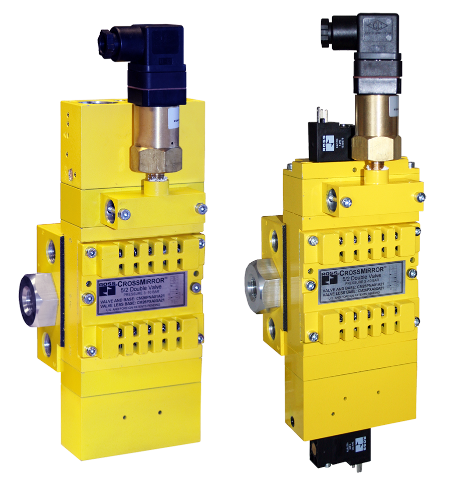
CrossMirror CM26 Series Double Valves Safety Category. 4 PL e, Internal Monitoring, Manual Reset
- Self-contained dynamic monitoring system requires no additional valve monitoring controls
- Dedicated reset; requires an overt act to reset unit after lockout
- Dual stainless steel spools construction
- Status indication switch (ready-to-run) to inform machine controller of valve condition
- The Pressure switch provides a signal when valve is in a faulted position
- Base mounted; manifoldable for multi-valve applications
- SISTEMA Library available for download
CrossMirror CM26 Series Double Valves Product Overview
This valve is constructed with precision, stainless steel spools as the main valve elements, and is designed to offer added safety to the operation of many pneumatically controlled machines such as small size pneumatic cylinder-operated presses, valve operators, and safety latches
The valve has a self-contained monitoring system, requires no additional monitoring and is designed for Category 4, Performance Level e applications. Upon detecting a fault due to discordant spool valve action, the valve locks out and remains so until an overt reset signal (electrical solenoid or remote pneumatic) is applied. This prevents unintentional reset and further bolsters safety. The optional pressure switch provides valuable feedback to the operator regarding whether or not the valve is in “ready-to-run” condition.
Please refer to the side and below for links to easily navigate and download ROSS Controls CrossMirror CM26 Series Double Valves catalogs, installation instructions, and technical data. Additionally, you have the option to filter through all available options to CrossMirror CM26 Series Double Valves variant that meets your requirements.
loading...
loading...
Product Overview
The ROSS Controls CrossMirror CM26 Series Double Valves combine self-contained internal dynamic monitoring with a dedicated manual reset requirement to deliver Safety Category 4, Performance Level e (PL e) per ISO 13849-1 and Safety Integrity Level 3 (SIL 3) per IEC 61508 in a base-mounted, manifoldable valve configuration. The CM26 Series is purpose-built for applications where deliberate operator or maintenance intervention is required before the safety system can be re-enabled after a lockout condition.
The CM26 Series incorporates two parallel, precision stainless steel spool-and-sleeve valve elements operating as a single unit. The self-contained internal monitoring system continuously compares spool positions during each actuation and de-actuation cycle. Upon detecting a fault - such as discordant spool movement or an unexpected valve state - the CM26 locks out and remains locked out until an overt reset signal is deliberately applied. This lockout behavior prevents unintentional reset that could occur in automatic-reset systems, adding an additional human confirmation layer before resuming hazardous machine operation.
The dedicated reset can be accomplished by an electrical solenoid signal or a remote pneumatic signal, giving design engineers flexibility in how the reset is integrated into the machine control architecture. An optional pressure switch provides a ready-to-run status signal to the machine controller, allowing the controller to confirm the CM26 is in the correct state before initiating the next production cycle.
The CM26 Series is base mounted and manifoldable, enabling multiple valve units to be assembled on a common manifold base for multi-valve safety circuit installations. This manifold capability reduces installation footprint, simplifies tubing, and allows multiple safety valve functions to be served from a shared pneumatic supply without separate individual valve mounting hardware. Available in NPT and G (BSPP) thread options with electrical and pneumatic actuation variants at 24 VDC and 110/120 VAC.
Key Engineering Features
- Self-Contained Internal Dynamic Monitoring - All fault detection logic is built into the CM26 valve assembly. No external safety PLC, safety relay, or monitoring controller is required to achieve Category 4 PL e, simplifying safety circuit design.
- Dedicated Manual Reset - Prevents Unintentional Restart - After a lockout due to a detected fault or discordant spool action, the CM26 remains locked out until a deliberate overt reset signal is applied. This prevents unintentional machine restart after a safety event and adds a human confirmation requirement to the recovery sequence.
- Electrical Solenoid or Remote Pneumatic Reset Options - The dedicated reset can be delivered by an electrical solenoid actuated from the machine control panel or by a remote pneumatic pilot signal, giving design engineers flexibility in reset circuit integration.
- Dual Stainless Steel Spool Construction - Two precision stainless steel spools in aluminum spool-and-sleeve housings provide durability, corrosion resistance, and reliable spool positioning for accurate internal monitoring throughout the valve service life.
- Base Mounted - Manifoldable for Multi-Valve Installations - The CM26 base-mount design allows multiple valves to be mounted on a shared manifold base, reducing installation space, simplifying compressed air distribution, and enabling multi-valve safety circuit configurations from a single manifold.
- Integrated Pressure Switch Status Indicator - Optional integrated pressure switch provides a ready-to-run electrical signal to the machine controller. The switch signals fault or lockout state, allowing the controller to prevent cycle initiation when the CM26 is not in the ready-to-run condition.
- Safety Category 4 PL e, SIL 3 - Achieves the highest available safety performance for pneumatic safety valves through self-contained internal monitoring per ISO 13849-1 and IEC 61508.
- Full International Certification - DGUV, CE, CSA/UL, and EAC certifications satisfy safety compliance requirements across European, North American, and global markets.
- SISTEMA Library Available - Published SISTEMA data library available for download from rosscontrols.com to support ISO 13849-1 PL verification and machine safety circuit documentation.
- Integral Exhaust Silencer - Built-in exhaust silencer on all CM26 models reduces exhaust noise without requiring separate external silencer hardware.
Technical Specifications
General Specifications
| Parameter | Specification |
| Series | CM26 (CrossMirror) |
| Valve Function | Dual 5/2 Single Solenoid; Dual 5/2 Single Pilot |
| Construction | Double Spool and Sleeve (stainless steel spools, aluminum body) |
| Actuation | Electrical (solenoid) or Pneumatic (pilot) |
| Monitoring | Internal (self-contained dynamic monitoring) |
| Reset | Dedicated - Solenoid (electrical reset) or Air Remote (pneumatic reset) |
| Status Indicator | Pressure Switch (ready-to-run); included or not included depending on model |
| Status Indicator Connection | EN 175301-803 Form A |
| Solenoid Connection Type (Electrical Models) | EN 175301-803 Form C |
| Voltage (Electrical Models) | 24 VDC; 110/120 VAC |
| Base Size | 0 (manifold base) |
| Inlet Port Size | 1/4 inch or 3/8 inch |
| Outlet Port Size | 1/4 inch or 3/8 inch |
| Exhaust | Built-in silencer |
| Thread Types | NPT and G (BSPP) |
| Operating Pressure Max | 150 psi (10 bar) |
| Mounting | Base mount; manifoldable |
| Ambient Temperature Range | 40 to 122 F (4 to 50 C) |
| Media Temperature Range | 40 to 175 F (4 to 80 C) |
| Flow Media | Filtered air |
| Valve Body Material | Cast aluminum |
| Spool Material | Stainless steel |
| Seal Material | Buna-N |
| Safety Category | Category 4 |
| Performance Level | PL e |
| Safety Integrity Level | SIL 3 |
Flow Performance Data
Flow coefficient data for CM26 Series double valves. All flow values with built-in exhaust silencer. Two primary configurations shown.
| Configuration | Cv (1-2) | Cv (1-4) | Cv (2-3) | Cv (4-5) | Length | Width | Height | Weight |
| Electrical Reset, G Thread, 24 VDC (CM26PDA00B21) | 0.8 | 0.6 | 0.5 | 1.1 | 12.29 in (312.2 mm) | 4.74 in (120.4 mm) | 4.37 in (110.9 mm) | 5.85 lb (2.7 kg) |
| Air Remote Reset, NPT Thread, Pneumatic (CM26PNA00P11) | 0.8 | 0.6 | 0.5 | 1.1 | 10.89 in (276.6 mm) | 4.74 in (120.4 mm) | 4.37 in (110.9 mm) | 6.15 lb (2.79 kg) |
| Electrical Reset, G Thread, 3/8" Ports, 24 VDC (CM26PDA01A2X) | 0.8 | 0.6 | 0.5 | 1.1 | 10.14 in (257.6 mm) | 4.74 in (120.4 mm) | 3.35 in (85.1 mm) | 5.2 lb (2.4 kg) |
Certifications & Compliance
| Certification/Standard | Detail |
| Safety Category | Category 4 per EN ISO 13849-1:2015, achieved through self-contained internal monitoring with dedicated manual reset. |
| Performance Level | PL e per EN ISO 13849-1:2015 - the highest performance level for machinery safety functions. |
| Safety Integrity Level | SIL 3 per IEC 61508 - the highest SIL for pneumatic valve applications. |
| DGUV Certification | German Social Accident Insurance certification required for press safety circuit compliance in Germany and European markets. |
| CE Marking | CE certified for EU Machinery Directive compliance. |
| CSA/UL Certification | North American electrical and safety certification. |
| EAC Declaration | Eurasian Conformity Declaration for markets requiring EAC certification. |
| SISTEMA Library | Published SISTEMA safety data library available for ISO 13849-1 PL verification and safety circuit documentation. |
Typical Applications & Industries
Mechanical Power Presses with Manual Reset Requirements
- Safety control valve for pneumatic clutch/brake systems on full-revolution mechanical power presses where OSHA 29 CFR 1910.217 and ANSI B11.1 require that a safety circuit fault result in a stop that cannot be reset without deliberate operator action. The CM26 manual reset lockout satisfies this requirement without additional reset hardware.
- Press safety circuits where regulatory requirements or customer safety standards mandate that any valve fault condition require a qualified operator or maintenance person to deliberately acknowledge and reset the safety system before production can resume.
- Pilot circuit safety control for large-tonnage hydraulic and pneumatic presses on automotive stamping lines where manual reset after a safety event is required by the facility's machine safety management program.
Multi-Valve Manifold Safety Systems
- Multi-cylinder press lines where multiple CM26 valves are manifolded together to control several press stations from a shared pneumatic supply, reducing installation cost and space requirements while maintaining individual Category 4 monitoring and manual reset for each station.
- Transfer press and progressive die press safety circuit manifolds where each die station requires its own Category 4 safety valve with individual fault lockout and manual reset capability.
- Safety circuits on multi-actuator assembly machines where several pneumatic safety functions are consolidated on a common CM26 manifold base, simplifying compressed air distribution and maintenance access.
Robotic Work Cell Safety Gates and Perimeter Guards
- Pneumatic safety gate locking actuators on high-speed robot work cells where Category 4 PL e manual reset prevents the gate from being re-locked after a safety event until a qualified person confirms the cell is clear and applies the reset signal.
- Perimeter fence actuation systems on automotive body shop welding cells where the CM26 manual reset requirement prevents unintentional robot cell restart after an e-stop or light curtain trip.
- Pneumatic interlocking systems on large-area safety zones where gate reset requires deliberate action at a keyed reset station connected to the CM26 electrical solenoid reset input.
Hydraulic Press Pilot Control
- Redundant pneumatic pilot control for hydraulic press directional control valves where the CM26 safety valve controls the pneumatic pilot signal to the main hydraulic valve, providing Category 4 monitored safety control of the press ram with manual reset after any fault.
- Hydraulic press counterbalance valve pilot circuits where manual reset lockout ensures the counterbalance system cannot be re-enabled after a pressure loss event without deliberate operator confirmation.
- Hydraulic clamp and die lock actuator control circuits on transfer presses where the CM26 provides redundant pneumatic safety pilot control with fault lockout and manual reset.
Special Purpose Machines and Safety Latching
- Pneumatic safety latching mechanisms on industrial centrifuges, rotary tables, and indexing systems where an unexpected latch release during rotation would create a severe hazard, requiring manual reset confirmation before the latch can be re-engaged.
- Safety catch actuators on vertical slide and overhead ram mechanisms where the CM26 internal monitoring detects catch engagement failure and locks out, requiring manual reset before the next machine cycle.
- Pneumatic controlled access to hazardous process zones on chemical, pharmaceutical, and food processing equipment where entry system reset after a safety event requires deliberate human intervention at the CM26 reset station.
Wire, Cable, and Connector Assembly Equipment
- Terminal crimping and connector assembly press safety control where the CM26 manual reset provides Category 4 PL e safety assurance and requires deliberate reset after each jam or fault condition before production can resume.
- Pneumatic cut-off and staking machine safety circuits where manual reset after a blade or tool fault prevents the machine from resuming operation until a trained technician confirms the fault is cleared.
- Multi-station wire processing machinery where CM26 manifold installations control multiple cutting, stripping, and termination station safety functions from a single shared base.
Ordering and Model Number Configuration
CM26 Series double valves are ordered by specifying actuation type, reset type, thread type, port size, voltage (electrical models), and status indicator option. Example models: CM26PDA00B21 (electrical reset, G thread, 24 VDC, with pressure switch), CM26PNA00P11 (air remote reset, NPT thread, pneumatic, with pressure switch).
|
Model Number Structure: CM26 P DA 00 B 21
CM26 Series (CrossMirror 26 Series Double Valve)
P Product family code
DA Actuation and reset type code (DA = Solenoid actuation, Solenoid reset) (NA = Pneumatic actuation, Air remote reset)
00 Base and port size code
B Status indicator option (B = with pressure switch; N = no status switch)
21 Voltage and thread code (21 = 24 VDC, G thread) (11 = pneumatic, NPT thread) (2X = 24 VDC, G thread, alternate configuration) |
Reset options: Solenoid (electrical solenoid signal applied to dedicated reset input) or Air Remote (pneumatic pilot signal applied to remote reset port).
Solenoid connection type for actuation solenoids is EN 175301-803 Form C on all electrical actuation models.
Status indicator pressure switch connection type is EN 175301-803 Form A on all models with status switch.
For manifold mounting, order the appropriate manifold base separately to match the CM26 model configuration and number of valves.
Exhaust silencer is built into all CM26 models. No external silencer is required.
Maximum operating pressure is 150 psi (10 bar) for all CM26 models.
Accessories
Manifold Bases for Multi-Valve Installations
Common manifold bases allow multiple CM26 valve units to be mounted side-by-side and share a single pneumatic supply connection. Contact ROSS Controls for manifold base selection based on the number of valve positions and port size configuration required.
Integrated Pressure Switch (Status Indicator)
Factory-installed pressure switch provides a ready-to-run status signal (EN 175301-803 Form A) to the machine controller. The switch transitions when the CM26 is in a lockout or faulted condition, allowing the machine controller to inhibit cycle initiation until the CM26 has been deliberately reset to the ready-to-run state.
Remote Pneumatic Reset Line
For air remote reset configurations, a dedicated pneumatic pilot line connects the machine control panel reset pushbutton's air supply to the CM26 reset port. Ensure the reset pilot line is independent of the actuation pilot supply to prevent inadvertent reset during actuation.
Related Products & Accessories
- SV27 Series Sensing Valve (Category 2 PL c) - 27 Series poppet sensing valve with DPST position feedback for Category 2 PL c safety circuits. https://www.rosscontrols.com/en/series/1298-directional-control-valve-sv27-series
- 27 Series Soft Start EEZ-ON Valve - Soft start valve for controlled gradual pressure buildup at machine startup. Safety Category 1, PL c. https://www.rosscontrols.com/en/series/1299-27-series-soft-start-eez-on-valve
- RSe Series Double Valve (External Monitoring, Auto Reset) - Redundant double valve requiring external safety monitoring controller. Automatic reset for higher-cycle-rate applications. https://www.rosscontrols.com/en/series/1300-rse-series-double-valve
- 77 Series Double Valve (Internal Monitoring, Auto Reset) - Self-monitoring double valve with automatic reset for applications where deliberate manual reset is not required. https://www.rosscontrols.com/en/series/1301-77-series-double-valve
- Lockout Valves (L-O-X, 15 Series) - Pneumatic lockout valves for OSHA LOTO energy isolation compliance. https://www.rosscontrols.com/en/series/1287-lockout-valves-15-series
Frequently Asked Questions (FAQ)
Q: What is the key difference between the CM26 CrossMirror and the 77 Series Double Valve?
A: Both the CM26 and the 77 Series use self-contained internal monitoring to achieve Category 4 PL e without an external safety controller. The critical difference is reset behavior. The 77 Series resets automatically when both pilot signals are removed. The CM26 locks out after a fault and requires a deliberate overt reset signal (electrical solenoid or remote pneumatic) before the valve can return to the ready-to-run state. This manual reset requirement is mandatory in some regulatory frameworks and provides a human confirmation gate before machine restart.
Q: Why would an application require a manual reset valve instead of an automatic reset?
A: Certain safety regulations, customer safety standards, and risk assessments require that after a safety circuit fault, the machine cannot restart automatically. The restart must require a deliberate act by a qualified person who physically confirms the hazard is cleared. OSHA, EN ISO 13849-1, and industry-specific standards like ANSI B11 and EN 1088 for interlocking devices all address reset requirements. In these cases, the CM26 manual reset satisfies the requirement without adding a separate external reset module to the safety circuit.
Q: How does the CM26 lockout differ from a simple valve fault stop?
A: A simple fault stop de-energizes the valve and stops machine motion, but the machine could restart automatically once the fault condition clears if the control system allows it. The CM26 lockout prevents the valve from returning to the ready-to-run state even after the fault clears, until the dedicated reset signal is deliberately applied. This means the machine stays stopped until a person physically performs the reset action, confirming the area is safe and the fault has been addressed.
Q: What are the reset options for the CM26?
A: The CM26 offers two reset options: electrical solenoid reset, where the machine control panel reset pushbutton energizes a dedicated reset solenoid on the CM26; and air remote reset, where a pneumatic pilot signal from a remote air-operated pushbutton or valve applies the reset signal. Both options require a deliberate operator or maintenance action to apply the reset signal.
Q: Can multiple CM26 valves be manifolded together?
A: Yes. The CM26 Series is specifically designed to be manifoldable. Multiple CM26 valve units can be assembled on a common manifold base, sharing a single pneumatic supply connection. This reduces the number of individual pneumatic connections, minimizes installation space, and simplifies maintenance. Each CM26 valve on the manifold operates independently with its own internal monitoring and dedicated lockout/reset function.
Q: What safety performance level does the CM26 achieve?
A: The CM26 CrossMirror Series achieves Safety Category 4, Performance Level e (PL e) per ISO 13849-1 and Safety Integrity Level 3 (SIL 3) per IEC 61508 through its self-contained internal dynamic monitoring system. This is the highest available safety performance for pneumatic double valves.
Q: Does the CM26 require an external safety PLC or monitoring controller?
A: No. The CM26 self-contained internal monitoring system detects discordant spool positions and locks out without requiring an external safety PLC or monitoring relay. The machine controller simply needs to monitor the optional pressure switch status indicator to know whether the CM26 is in the ready-to-run or locked-out state.
Q: What certifications does the CM26 carry?
A: The CM26 carries DGUV certification, CE certification for EU Machinery Directive compliance, CSA/UL certification for North American markets, and an EAC Declaration. Safety performance is Category 4 PL e per ISO 13849-1 and SIL 3 per IEC 61508.
Q: What does the pressure switch status indicator tell the machine controller?
A: The pressure switch (where included) signals the ready-to-run or not-ready-to-run state of the CM26. When the CM26 is in the ready-to-run condition with both spools in the normal home position, the pressure switch signals ready. When the CM26 has detected a fault and locked out, the pressure switch signals not-ready. The machine controller monitors this signal and inhibits cycle initiation when the CM26 is not in the ready-to-run state.
Q: What is the maximum operating pressure?
A: Maximum operating pressure for all CM26 Series models is 150 psi (10 bar). Operating below this maximum is required to maintain internal monitoring performance and spool positioning accuracy.
Q: Is a SISTEMA library available for the CM26?
A: Yes. ROSS Controls publishes a SISTEMA library file for the CM26 CrossMirror Series, available for download at rosscontrols.com. The library contains the required safety parameters (B10D, MTTFd, DC) for ISO 13849-1 PL e verification and machine safety documentation.
Q: Are NPT and G thread options available?
A: Yes. The CM26 is available with both NPT and G (BSPP) thread options. Thread type is specified at the time of order. Both 1/4 inch and 3/8 inch port sizes are available depending on the specific model configuration.
Installation & Maintenance Guidelines
- Mount the CM26 valve on its base in the correct orientation. Ensure the base port connections match the piping for inlet, outlet, and exhausting before securing the mounting hardware.
- For manifold installations, mount all CM26 valve units on the manifold base before connecting the shared supply line. Verify all inter-valve connections are sealed and no cross-port leakage is present.
- The dedicated reset solenoid (for solenoid reset models) must be wired to a separate, dedicated reset circuit that is independent from the actuation solenoid circuit. Never combine the reset and actuation solenoid outputs on the same controller output channel.
- For air remote reset models, connect the remote pneumatic reset pilot line from the panel-mounted reset pushbutton to the CM26 reset port. Confirm the reset pilot supply is independent of the actuation pilot supply.
- Connect the optional pressure switch status indicator to the machine controller using an EN 175301-803 Form A connector. Program the controller to inhibit cycle initiation when the status indicator signals not-ready.
- Confirm solenoid actuation voltage matches the CM26 model voltage rating (24 VDC or 110/120 VAC). Solenoid connection type is EN 175301-803 Form C.
- Operating pressure must not exceed 150 psi (10 bar). Overpressure can affect spool positioning and internal monitoring performance.
- Supply filtered compressed air to the valve. Contamination affects stainless steel spool movement and internal monitoring response.
- After installation, perform a full functional test: actuate the valve and confirm correct output. Then simulate a fault condition (apply only one pilot signal, or introduce a test discordance) and confirm the CM26 locks out and the status indicator signals not-ready. Verify the valve cannot be actuated in the lockout state. Apply the reset signal and confirm the CM26 returns to ready-to-run. Document all test results for safety validation records.
- Establish a documented proof test interval and procedure consistent with the PFD calculation for the safety function. Annual proof testing is a recommended starting point for most applications.
Warranty & Global Support
ROSS Controls provides a one-year warranty on all CM26 CrossMirror Series products, covering defects in material and workmanship from the date of purchase.
Technical support for CM26 installation, manifold configuration, reset circuit design, and safety circuit integration is available from ROSS Controls USA at (800) 438-7677 or +1-248-764-1800.
Global ROSS offices provide local technical support in the USA (Ferndale, Michigan headquarters), Canada, Brazil, Germany, France, United Kingdom, India, China, and Japan.
For SISTEMA data, DGUV certification documentation, manifold base options, dimensional drawings, and CAD models, visit the CrossMirror CM26 product page at rosscontrols.com.
Download Catalog: https://www.rosscontrols.com/en/series/1302-crossmirror-cm26-series-double-valves
Download Documents
CrossMirror CM26 Series Double Valves
