Miniature Series Port Sizes 1/8" & 1/4"; Flow to 40 scfm (1133 l/min)
- Inline relief valve
- Diaphragm construction
- Self-relieving
Relief Valves Miniature Series Product Overview
The Miniature Series Relief Valves are designed as inline relief valves, offering a compact solution for pressure relief. These valves feature diaphragm construction, ensuring precise pressure control. They are also self-relieving, providing efficient and reliable relief in various applications.
Please refer to the side and below for Relief Valves Miniature Series catalogs, installation instructions, and technical data. Additionally, you have the option to filter through all available Relief Valves Miniature Series variant that meets your requirements.
loading...
loading...
Product Overview
The ROSS Controls is a family of compact inline pneumatic relief valves designed for overpressure protection of small-bore pneumatic circuits in 1/8" and 1/4" port sizes. With flow capacity up to 40 scfm (1133 l/min) and four adjustable pressure ranges covering 1 to 140 psig (0.07 to 9.6 bar), the series provides a wide adjustment envelope for small-bore instrument air, tool supply, and pneumatic control circuits.
Relief valves serve a fundamentally different function from pressure regulators: rather than reducing supply pressure to a set working level, a relief valve remains closed under normal operating conditions and opens only when downstream pressure exceeds the set relief pressure. This makes them the appropriate choice for overpressure protection of fixed-pressure circuits, downstream protection of non-relieving regulators, and safety relief in pneumatic systems where unexpected pressure buildup must be vented to prevent equipment damage or safety hazards.
The Series uses diaphragm construction, which provides high sensitivity to excess pressure conditions and allows the valve to open and close sharply and repeatably at the set pressure. The large diaphragm area relative to the valve seat geometry mirrors the sensing approach of the precision regulator family, enabling the series to respond precisely to overpressure conditions without significant pressure overshoot before relief commences. The self-relieving nature of the design ensures that vented air releases at the valve body rather than requiring separate exhaust piping in most installations.
Four factory-configured pressure ranges (1-15, 1-30, 1-50, and 1-140 psig) are available, each using a calibrated internal spring for optimum sensitivity at the target relief pressure. Both NPTF and G (BSPP) thread standards are available. Optional Fluoroelastomer seals are available for applications where the standard Nitrile seals are not chemically compatible with the compressed gas medium.
Key Engineering Features
- Diaphragm Construction for High Sensitivity - Large diaphragm sensing area relative to the valve seat provides precise, repeatable opening and closing at the set relief pressure, minimizing pressure overshoot before relief commences.
- Four Selectable Pressure Ranges - Available in 1-15, 1-30, 1-50, and 1-140 psig factory-configured ranges, each using a calibrated spring for optimum sensitivity and accuracy at the target relief pressure. Selecting the range closest to the target relief pressure yields best regulation.
- Compact Miniature Footprint - Body dimensions of 1.6" x 2.7" x 0.4" (41 x 68 x 10 mm) at 0.24 lb (0.11 kg) allows installation at individual actuator supply points, in instrument enclosures, and in confined panel spaces.
- Self-Relieving Design - Vents excess downstream pressure through the valve body to atmosphere when system pressure exceeds the relief set point, without requiring separate exhaust piping in most installations.
- High Inlet Pressure Rating - Accepts inlet supply pressures up to 300 psig (21 bar), enabling use on high-pressure circuits where the relief set point is well below the supply pressure.
- Wide Adjustment Range in Each Pressure Band - Within each pressure range, the adjustment screw allows continuous set point adjustment from the minimum to maximum of the selected range, providing field adjustability without replacing the spring.
- Fluoroelastomer Seal Option - Optional Fluoroelastomer seals extend chemical compatibility to applications where standard Nitrile seals are not suitable for the gas medium or trace contaminants.
- Panel Mount Capability - Compatible with 1-3/16" (30 mm) panel cutout for flush mounting in control panels, with front and rear 1/8" NPT gauge ports for pressure monitoring.
- NPTF and G Thread Standards - Available in both NPTF and G (BSPP) thread standards for compatibility with North American and international pneumatic systems.
- Aluminum Body Construction - Aluminum body with Acetal dome and knob provides corrosion resistance for instrument air and clean compressed air service within the rated temperature range.
Technical Specifications
General Specifications
| Parameter | Specification |
| Series | Miniature Relief Valves |
| Type | Inline Relief Valve |
| Construction | Diaphragm, Self-relieving |
| Port Sizes | 1/8", 1/4" |
| Thread Types | NPTF (American) and G (BSPP/ISO) |
| Maximum Flow | 40 scfm (1133 l/min) |
| Inlet Pressure (Maximum) | 300 psig (21 bar) |
| Relief Pressure Range 1 | 1 to 15 psig (0.07 to 1.0 bar) |
| Relief Pressure Range 2 | 1 to 30 psig (0.07 to 2.1 bar) |
| Relief Pressure Range 3 | 1 to 50 psig (0.07 to 3.4 bar) |
| Relief Pressure Range 4 | 1 to 140 psig (0.07 to 9.6 bar) |
| Pressure Gauge Port | 1/8" NPT, front and rear |
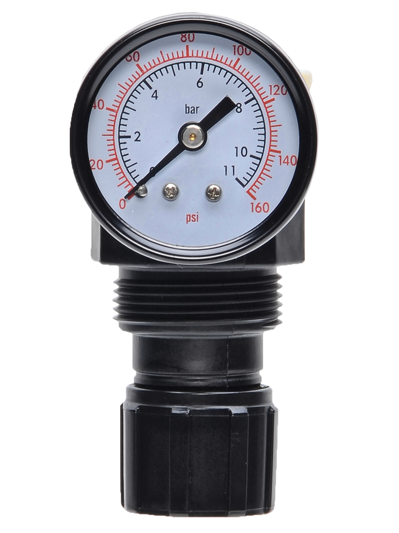
| Pressure Gauge (optional) | 0 to 160 psig (0 to 11 bar) |
| Panel Mounting Hole | 1-3/16" (30 mm) diameter |
| Flow Media | Filtered compressed air |
| Body Material | Aluminum |
| Dome and Knob Material | Acetal |
| Seal Material | Nitrile (standard); Fluoroelastomer (optional) |
| Dimensions (L x H x W, less gauge) | 1.6" x 2.7" x 0.4" (41 x 68 x 10 mm) |
| Depth (less gauge) | 1.6" (41 mm) |
| Weight (less gauge) | 0.24 lb (0.11 kg) |
Temperature Ratings
Temperature limits apply to both ambient environment and the compressed air media. Standard Nitrile seals cover most indoor industrial and laboratory applications. Fluoroelastomer seals are available for special applications.
| Configuration | Ambient Temperature | Media Temperature |
| Standard (Nitrile Seals) | 40 to 125 F (4 to 52 C) | 40 to 125 F (4 to 52 C) |
| Optional (Fluoroelastomer Seals) | Consult ROSS Controls | Consult ROSS Controls |
Flow Performance Data
Flow performance data at 1/8" and 1/4" port sizes. Maximum 40 scfm at full-open relief condition. Relief flow at set point varies by pressure range and inlet pressure; typical relief flows are 10 to 20 scfm at rated conditions.
| Port Size | Max Relief Flow scfm (l/min) | Inlet Pressure psig | Relief Ranges psig | Weight lb (kg) |
| 1/8" | 40 (1133) | 300 max | 1-15, 1-30, 1-50, 1-140 | 0.24 (0.11) |
| 1/4" | 40 (1133) | 300 max | 1-15, 1-30, 1-50, 1-140 | 0.24 (0.11) |
Certifications & Compliance
| Certification/Standard | Detail |
| Thread Standards | NPTF per ANSI/ASME B1.20.3 and G (BSPP) per ISO 228-1. |
| Material Compliance | Aluminum body, Acetal dome and knob, Nitrile or Fluoroelastomer seals comply with standard industrial compressed air component requirements. |
| CE Marking Eligibility | Designed for compliance with EU Machinery Directive requirements. Consult ROSS Controls for specific CE documentation. |
Typical Applications & Industries
Downstream Protection of Non-Relieving Regulators
- Downstream overpressure protection for non-relieving pressure regulators in circuits where the regulator cannot vent excess pressure back through its body. The Series relief valve provides the required relief path when upstream pressure rises above the regulator set point.
- Protection of instrument air circuits served by non-relieving regulators in pneumatic control systems, preventing pressure buildup in the downstream circuit when the non-relieving regulator's set point is raised.
- Protection of closed pneumatic loops where downstream pressure can increase due to thermal expansion of trapped air, prevented from venting by a non-relieving regulator or closed valve.
- Protection of pressure-sensitive instruments and gauges downstream of non-relieving regulators in test and measurement applications, where pressure overshoot could damage calibrated equipment.
- Safety relief in circuits where a manually operated non-relieving regulator could be inadvertently set too high, with the series providing a maximum-pressure safety backup.
Pneumatic Tool and Actuator Overpressure Protection
- Overpressure protection for pneumatic tools at individual stations where supply pressure could exceed the tool's maximum rated inlet pressure due to regulator failure or supply system overpressure events.
- Small-bore cylinder and actuator protection in automation and assembly equipment, where excess pressure could damage cylinder seals, mechanical stops, or connected mechanisms.
- Pneumatic gripper and end-of-arm tooling protection on robots and automation systems, where force-limiting applications require strict maximum pressure control and the relief valve serves as a pressure-limiting backup.
- Press and clamp actuator protection where mechanical stops could be overloaded if supply pressure exceeds design limits.
- Pneumatic brake and clutch actuator protection for controlled maximum engagement force, with the series ensuring maximum actuation pressure is never exceeded regardless of supply system variations.
Instrumentation and Control System Protection
- Overpressure protection for pneumatic instrument signal lines (typically 3-15 psig or 6-30 psig) in process control systems where instrument supply variations or control system faults could produce excess pressure damaging to connected instruments.
- Protection of pneumatic control system components (valves, actuators, I/P transducers) operating at low instrument air pressures in the 1-15 psig or 1-30 psig ranges.
- Gauge protection: installing a Series relief valve upstream of a calibrated pressure gauge prevents overpressure damage to the gauge mechanism during system pressure excursions.
- Laboratory pneumatic system safety: protecting sensitive bench-top equipment, test fixtures, and experimental apparatus from overpressure conditions caused by operator error or supply system faults.
- Analyzer system protection for process gas analyzers and sample conditioning systems where supply air must remain below a strict maximum pressure to protect analyzer valves and sample handling components.
Low-Pressure Pneumatic Control Applications
- Piston seal condition monitoring systems operating at 1-15 psig where the series provides maximum-pressure safety for differential pressure sensing elements.
- Pneumatic floats and level control systems in process tanks where low-pressure air supply (1-5 psig) to floats or bubblers must be protected from supply pressure excursions.
- Pneumatic position sensors and feedback devices requiring very low air pressure levels, protected by the 1-15 psig range Series relief valve.
- Air bearing and air cushion systems in conveyor and material handling applications where air pad pressure must not exceed design limits to prevent part damage or safety hazards.
- Low-pressure packaging and forming applications where consistent forming pressure at very low levels requires both a precision regulator and downstream relief valve protection.
Ordering and Model Number Configuration
The ROSS model numbers identify the port size and pressure range. Four pressure ranges are available: 1-15, 1-30, 1-50, and 1-140 psig. Both NPTF and G thread options are available at each port size and pressure range combination.
|
Model Number Structure: 5210B [Port] [Range]
5210B1001 - 1/8" NPTF, 1-140 psig 5210B1002 - 1/8" NPTF, 1-15 psig 5210B1003 - 1/8" NPTF, 1-30 psig 5210B1004 - 1/8" NPTF, 1-50 psig 5210B2001 - 1/4" NPTF, 1-140 psig 5210B2002 - 1/4" NPTF, 1-15 psig 5210B2003 - 1/4" NPTF, 1-30 psig 5210B2004 - 1/4" NPTF, 1-50 psig
Prefix C = G (BSPP) thread C5210B1001 = 1/8" G, 1-140 psig C5210B2001 = 1/4" G, 1-140 psig (etc.)
Port code: 1 = 1/8", 2 = 1/4" Range code: 001=1-140 psig, 002=1-15 psig, 003=1-30 psig, 004=1-50 psig |
Select the pressure range closest to the required relief set point for optimum spring sensitivity and accurate relief pressure. Ranges are: 1-15 (code 002), 1-30 (code 003), 1-50 (code 004), 1-140 (code 001) psig.
For models with increased sensitivity at very low pressure settings (below 5 psig), consult ROSS Controls for special configurations.
G (BSPP) thread models prefix with C (e.g., C5210B1001). NPTF and G threads are not interchangeable.
Fluoroelastomer seal option is available for special chemical compatibility requirements. Contact ROSS Controls to specify.
Pressure gauge is not included standard. 0-160 psig gauges are available from ROSS Controls for the 1/8" NPT gauge ports.
Standard Model Numbers - 1/8" Port
| Port Size | Thread | Pressure Range psig (bar) | Model Number |
| 1/8" | NPTF | 1-15 (0.07-1.0) | 5210B1002 |
| 1/8" | NPTF | 1-30 (0.07-2.1) | 5210B1003 |
| 1/8" | NPTF | 1-50 (0.07-3.4) | 5210B1004 |
| 1/8" | NPTF | 1-140 (0.07-9.6) | 5210B1001 |
| 1/8" | G (BSPP) | 1-15 (0.07-1.0) | C5210B1002 |
| 1/8" | G (BSPP) | 1-30 (0.07-2.1) | C5210B1003 |
| 1/8" | G (BSPP) | 1-50 (0.07-3.4) | C5210B1004 |
| 1/8" | G (BSPP) | 1-140 (0.07-9.6) | C5210B1001 |
Standard Model Numbers - 1/4" Port
| Port Size | Thread | Pressure Range psig (bar) | Model Number |
| 1/4" | NPTF | 1-15 (0.07-1.0) | 5210B2002 |
| 1/4" | NPTF | 1-30 (0.07-2.1) | 5210B2003 |
| 1/4" | NPTF | 1-50 (0.07-3.4) | 5210B2004 |
| 1/4" | NPTF | 1-140 (0.07-9.6) | 5210B2001 |
| 1/4" | G (BSPP) | 1-15 (0.07-1.0) | C5210B2002 |
| 1/4" | G (BSPP) | 1-30 (0.07-2.1) | C5210B2003 |
| 1/4" | G (BSPP) | 1-50 (0.07-3.4) | C5210B2004 |
| 1/4" | G (BSPP) | 1-140 (0.07-9.6) | C5210B2001 |
Accessories
Pressure Gauges
0 to 160 psig (0 to 11 bar) pressure gauges compatible with the 1/8" NPT gauge ports on the series. Install to monitor downstream circuit pressure relative to the relief set point.
Panel Mount Nut
Panel mount nut for flush mounting through a 1-3/16" (30 mm) panel cutout. Secures the series in control panels and operator stations.
Upstream Precision Regulators
ROSS Controls 120 Series Miniature Precision Regulators are commonly installed upstream of the series in small-bore circuits requiring both precision regulation and downstream overpressure protection.
Related Products & Accessories
- 128 Series High-Flow Relief Valves - Inline high-flow relief valve for 1" port, flow to 450 scfm, for large-volume overpressure protection applications. https://www.rosscontrols.com/en/series/128-high-flow-series
- 120 Series Miniature Precision Regulator - Miniature inline precision regulator commonly paired upstream of the series for precision regulation with downstream relief protection. https://www.rosscontrols.com/en/series/120-miniature-precision-series
- 121 Series Full-Size Precision Regulator - Full-size modular precision regulator for 1/4" to 3/4" ports, used with non-relieving option requiring downstream relief protection. https://www.rosscontrols.com/en/series/121-full-size-precision-series
- ROSS FRL Filters (Miniature Series) - Miniature upstream filters for particulate removal to protect the series valve seat. https://www.rosscontrols.com/en/categories/filters
- ROSS Directional Control Valves - Pneumatic directional control valves for circuit isolation and directional control upstream of protected circuits. https://www.rosscontrols.com/en/categories/directional-control-valves
- ROSS Pressure Switches - Pressure switches for electronic monitoring of downstream pressure in circuits also protected by Series relief valves. https://www.rosscontrols.com/en/categories/pressure-switches
Frequently Asked Questions (FAQ)
Q: What is the difference between a relief valve and a regulator?
A: A pressure regulator is a normally-open device that continuously modulates downstream pressure to a set level. A relief valve is a normally-closed device that stays closed under normal conditions and opens only when downstream pressure exceeds the relief set point, venting excess pressure. Relief valves provide overpressure protection; regulators provide pressure reduction and control. Many circuits use both: a regulator to set working pressure and a relief valve to protect against overpressure faults.
Q: When is a downstream relief valve required even when using a self-relieving regulator?
A: A self-relieving regulator can vent downstream pressure through its body when set point is reduced. However, it does not vent when downstream pressure rises above the set point due to temperature increases, flow reversals, or other system causes. If these conditions can occur, a relief valve provides the required safety relief. Additionally, non-relieving regulators always require a downstream relief valve to vent pressure when set point is reduced.
Q: How do I select the correct pressure range for the series?
A: Select the pressure range whose maximum is closest to (but greater than) the required relief set point. For example, if the relief set point is 25 psig, select the 1-30 psig range (not the 1-50 psig range). Using a range closer to the target pressure results in a more sensitive spring with more accurate and repeatable cracking and reseat pressure.
Q: What is the cracking pressure and how does it relate to set point?
A: The cracking pressure is the downstream pressure at which the relief valve begins to open. In diaphragm relief valves, the cracking pressure is very close to the set point, and the valve opens progressively as downstream pressure rises above cracking pressure. Full rated flow is reached when downstream pressure is somewhat above the cracking pressure, depending on the spring rate and diaphragm area.
Q: What is the maximum inlet pressure for the series?
A: The Series accepts inlet pressures up to 300 psig (21 bar). The relief set point is always set at or below the system working pressure. The inlet pressure itself does not trigger relief; the valve responds to downstream pressure exceeding the relief set point.
Q: Can the series be used for very low pressure relief (below 5 psig)?
A: For set points below 5 psig, the standard 1-15 psig range spring may have insufficient sensitivity for accurate, repeatable relief. ROSS Controls offers special configurations with increased sensitivity at very low pressure settings. Contact ROSS Controls directly for sub-5 psig applications.
Q: What flow capacity does the series provide in relief?
A: The Series provides maximum relief flow of 40 scfm (1133 l/min) through either 1/8" or 1/4" port size. Typical relief flows at rated conditions are 10 to 20 scfm. For applications requiring higher relief flow capacity, the 128 Series High-Flow Relief Valve (flow to 450 scfm) should be evaluated.
Q: Where should the series be installed in the circuit?
A: Install the series downstream of the protected component - for example, downstream of a non-relieving regulator, between a regulator and a sensitive instrument, or at the inlet of a pressure-sensitive actuator. The relief valve outlet exhausts to atmosphere and should be located where venting air safely dissipates, away from operators and heat sources.
Q: Are Fluoroelastomer seals standard?
A: No. Nitrile seals are standard for compressed air service. Fluoroelastomer seals are available as a special option for applications where trace chemicals, solvents, or gas compositions are not compatible with Nitrile. Contact ROSS Controls to specify Fluoroelastomer seals when ordering.
Q: What gauge is compatible with the series gauge ports?
A: The Series has 1/8" NPT gauge ports front and rear. A compatible gauge reads 0 to 160 psig (0 to 11 bar). Install a gauge in either the front or rear port; plug the unused port with a 1/8" NPT plug.
Q: Can the series be used in reverse flow (downstream to upstream)?
A: No. The Series is designed for standard flow from inlet (supply side) to outlet (circuit side). Reverse flow would be from the protected downstream circuit back toward the supply. The Series is not a reverse-flow relief valve. Consult ROSS Controls for reverse-flow relief applications.
Q: What is the operating temperature range?
A: Standard Nitrile seals provide a temperature range of 40 to 125 F (4 to 52 C) for both ambient and media. For higher-temperature relief applications, or for chemical compatibility at non-standard temperatures, consult ROSS Controls for Fluoroelastomer seal options.
Installation & Maintenance Guidelines
- Install the series downstream of the component requiring overpressure protection. For non-relieving regulators, install the relief valve immediately downstream of the regulator in the circuit.
- Mount the valve with the adjusting knob accessible for set point adjustment. Panel mounting in a 1-3/16" (30 mm) cutout with a panel mount nut is appropriate for control panel installations.
- Ensure the relief valve outlet exhausts to a safe location. The relief valve vents to atmosphere; locate the outlet where released air will not pose a hazard to personnel or equipment.
- Set the relief pressure by turning the adjusting knob clockwise to increase and counterclockwise to decrease. Set approximately 5 to 10 psig above normal working pressure to prevent nuisance opening under normal flow and pressure transient conditions.
- Verify the relief set point by slowly increasing downstream pressure (using a separate pressure source or restricting downstream flow) until the valve cracks open, noting the opening pressure with a gauge.
- Install a minimum 5-micron upstream filter to protect the valve seat from particulate contamination that could prevent full reseating after a relief event.
- Do not install the series where downstream pressure could exceed the 300 psig (21 bar) maximum inlet rating. The valve body is not designed for supply-side pressures above this limit.
- Plug unused 1/8" NPT gauge ports to prevent air release and contamination ingress.
- Maintain ambient temperature within 40 to 125 F (4 to 52 C) for standard Nitrile seal operation.
- After commissioning, test the relief function by intentionally increasing downstream pressure above the set point to verify opening and reseating. Document the actual cracking pressure for maintenance records.
Warranty & Global Support
ROSS Controls provides a one-year warranty on all products, covering defects in material and workmanship from the date of purchase.
Technical support for the series and relief valve application design is available through ROSS Controls USA at (800) 438-7677.
Global support through ROSS Controls offices in Canada, Brazil, Germany, France, United Kingdom, India, China, and Japan.
Visit rosscontrols.com for Series technical data, dimensional drawings, pressure range selection guidance, and authorized distributor information.
Download Catalog: https://www.rosscontrols.com/en/documents
Download Documents
Miniature Series
