Choosing the most appropriate safety function will depend on the risks, desired outcomes, potential failure modes, and residual risks. In all cases, the safety logic device will drop power to the output devices. The circuit is dependent upon the output device performing the safety function when signaled to do so. Choosing the right valve requires an understanding of the operation and failure modes of the valves that might be used to implement the safety function.
Safety Functions
Complete safety functions are made of input devices, logic devices, and output devices. The safety input device is the trigger for the safety function. The safety logic device monitors the input device and decides on how to control the output devices. The safety logic device also monitors the feedback signals from the output device(s).
Safety Function
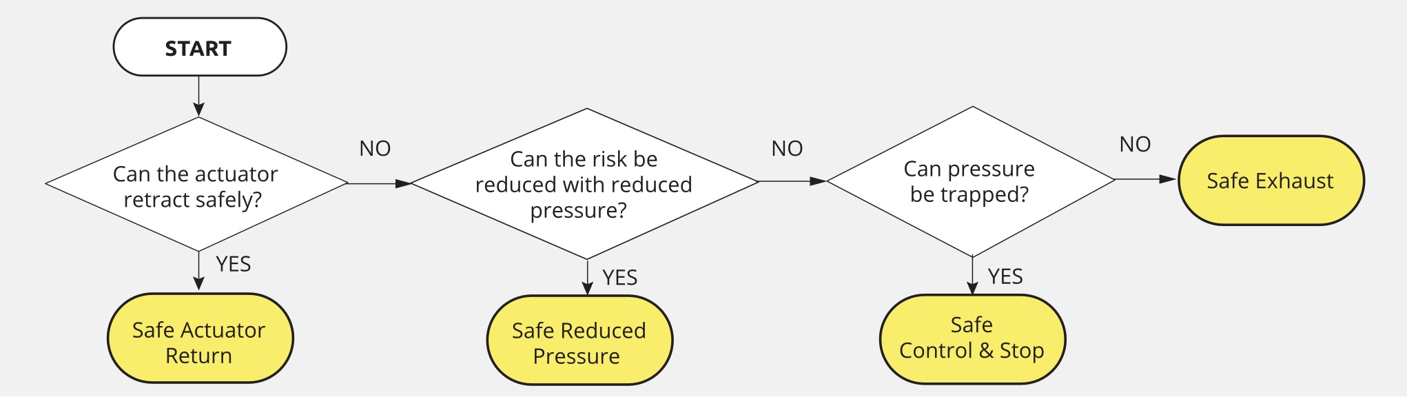
Safety reaction tables can be used to determine how individual actuators are to be controlled based on safety-triggering events (the table below is just an example).
| Actuator List | ||||
|---|---|---|---|---|
| Triggering Devices | Clamp Cylinder | Press Cylinder | Riveting Motor | Slide Cylinder |
| Emergency Stop | Safe Exhaust | Safe Exhaust | Power Isolation | Safe Exhaust |
| Light Controls | Safe Pressure | Safe Control & Stop | Power Isolation | Safe Return |
| Door Switch | ||||
Failure Modes
Understanding the failure modes of the devices chosen is very important in the design process when you want to fail to a safe condition. The most common valve failure is when a valve does not shift properly, either energizing or de-energizing, and the valve’s function is not performed. This can cause unexpected motion – either at the wrong time or even in the wrong direction. Depending on the application, this could lead to a critical situation.
There are, however, many other common valve failure modes and reasons for the failures. The tables below list common fluid power valve failure modes and some failure modes that are specific to certain valve functions.
| Standard Fluid Power Valve Failure Modes | ||||
|---|---|---|---|---|
| Problem | Result | Considerations | ||
| Pilot pressure is reduced or lost | Valve will return to mechanically offset (OFF) position. | Ensure offset (OFF) position is the fail to safe position. | ||
| Internal wear causing leakage | Not possible to pre-define as depends on valve design. | Ensure valve design does not allow for unsafe condition. | ||
| Dirt, grit, or rust enters valve | Valve may stick (see valve sticking). | Make sure pipes are clean, pipe take not used, filter hydraulic oil and air. | ||
| Valve spool sticks | Valve will not return to mechanically offset (OFF) position. Valve can be in any number of crossover conditions. |
*Requires that 2nd valve be used and placed in a circuit that allows both to function properly. | ||
| Failure of valve actuator | If actuator fails in de-actuated position, valve will return to mechanically offset (OFF) position. If actuator fails in actuated position, valve will stay actuated. |
*Requires that 2nd valve be used and placed in a circuit that allows both to function properly. | ||
| Failure of solenoid coil | Valve will return to mechanically offset (OFF) position. | Ensure offset (OFF) position is the fail to safe position. | ||
| Failure subject to excessive flow | Valve may shift without a signal. | Ensure valve is designed to prevent such from causing accidental shifting, particularly in hydraulics. | ||
| Failure Modes Associated with Certain Valve Functions | ||||
|---|---|---|---|---|
| Valve Type | Faults | Worse Case Faulted Outcome | ||
| 3/2 Normally Closed Spring Return | Air continues to be supplied | |||
| 5/2 Spring Return | Motion continues at full force, does not reverse | |||
| 5/2 Detented | Motion will continue until end of stroke or reverses | |||
| 5/3 Open Center, Closed Center, or Power Center | Pilot or spool stick Broken components (spring, seals, detent), Contamination |
Motion continues at full force or reverses | ||
| Pilot Operated Check | Motion due to opposite end pressure or gravity | |||
| Flow Control | Speed control not effective, exhaust restricted | |||
| Soft Start | Speed control not effective, exhaust restricted | |||
| Figure 5-1 *Same as control-reliable valve except you must also design in monitor. | ||||
Category 3 and 4 valves are used to prevent these types of failures from causing the loss of the safety function. The redundancy (or structure) and the monitoring create fail-to-safe devices. If one valve element malfunctions, the second valve element can still perform the safety function. However, other factors will affect when a dual safety valve has a fault, such as increased stopping time. A change in the normal flow path of a faulted valve will affect the time it takes to exhaust the pressure or add pressure in a safe return function. This should be considered in any safe distance calculations.
Residual Risk
Quite often, risk mitigation attempts can result in unacceptable levels of residual risk. Because of this, the risk assessment process is iterative. The first attempt may leave residual risk that is deemed unacceptable, and, therefore, requires at least a second attempt to reach an acceptable level of risk. The process must be repeated until an acceptable level of risk is achieved. The table below represents a list of common hazards and associated residual risks for each of the four safety functions. Other safety functions may be available that can be used to address the residual risks until an acceptable level of risk is achieved.
| Cause of Hazard | Safety Function | Advantage | Residual Risk |
|---|---|---|---|
| Cylinder motion/point of operation | Safe Exhaust | Remove motive force from actuators Can supply a zone or cell |
Reapplication of pressure, gravity |
| Safe Cylinder Return | Single actuator control | Retract motion, loss of supply pressure | |
| Safe Control Stop | Single actuator control | Trapped pressure, leakage | |
| Clamp (Pinch point) | Safe Reduced Pressure / Force | Reduce force from actuators Can supply a zone or cell |
Pinch points remain at reduced force / pressure |
| Residual Risk | Safety Function | New Residual Risk |
|---|---|---|
| Reapplication of pressure | Soft-Start | Entire system may not be pressurized (i.e., downstream of 5/3 CC) |
| Reapplication of pressure | Flow Control | No back pressure for first stroke |
| Gravity | Load Holding | Leakage, slow motion, must be blocked for maintenance |
| Loss of supply pressure | Check Valve on supply | Leakage, slow motion, must be blocked for maintenance |
| Leakage | Periodic testing of safety circuit | Slow motion |
| Trapped pressure | Trapped pressure | Leakage, slow motion, must be blocked for maintenance |
There are four primary solutions for abating pneumatic actuator-associated risks:
- Block the air supply to the control valve and, therefore, to the actuators, with a 3/2 control reliable exhaust valve (Category 3 or 4). Use a safety-rated valve matched to the control category determined by your risk assessment. The advantage of this method is that one safety-rated exhaust valve can be used to remove the supply pressure from one or more directional control valves and actuators while helping maintain safety system control integrity. A safety-rated exhaust valve can supply a machine, cell, or zone.
In some cases, removing the supply pressure alone can leave a load free to fall or continue moving due to gravity or momentum. In addition to safe exhaust, you must consider the gravitational force and momentum operating on the mass of the load and apply a suitable solution to stop and hold the load in place. With the motive force removed, the suitable solution will be dependent upon the mass, the tooling, and the failure modes of the devices being used to maintain a safe state. Solutions may include the use of pilot-operated check valves to trap pressure beneficially, and/or safety catchers or rod locks to mechanically hold the actuator(s) without trapping pressure in the system. - Reverse the cylinder motion to a safe position by using a 5/2 control-reliable double valve. This will result in a safe state, provided a return stroke of the actuator does not post any additional risk. In the case of heat-sealing applications, this could be a very good solution. It would remove the heating element from the workpiece (fuel) as well as reverse the cylinder direction away from the pinch point.
- Stopping motion by trapping pressure in both ends of the cylinder can be accomplished with a safety-rated 4/3 or 5/3 closed center valve. Only a safety-rated closed center valve can be used to reach higher level control reliable safety-rated systems without the addition of other components mentioned in solution 1.
- Reduce the force or pressure to an acceptable level using a pressure select solution. This will supply higher pressure during normal operations but reduced pressure when safe operator access is required. This can be used to supply downstream valves. It is important to note that higher pressure may still be downstream depending on the type of actuator valve in the circuit. For example, a 5/3 closed-center valve will maintain the higher pressure until shifted, allowing the lower pressure into the system.
Fault Exclusion
Many of these are simply based on good engineering practices that are required in other standards. These ISO 13849-2 Annexes A-D provide information on fault exclusions for mechanical, pneumatic, hydraulic, and electrical systems respectively. Each of these sections looks at basic safety principles, and then faults and fault exclusions which are broken into valve function and specific failure modes. For the sake of brevity, the figures shown below are excerpts of the tables and not the complete tables.
One example of fault exclusion is that you can exclude that a valve will burst when it is used within its specifications. The manufacturer will have undergone the design and testing of the product. If the valve is third-party certified, this testing would be part of the documentation package and the technical file required for CE marking. This is an entirely reasonable fault exclusion.
ISO 13849-2 does not allow for fault exclusion of hoses in fluid power systems.
An additional hydraulic issue of note includes proper fastening. It specifically mentions manufacturers’ application notes and proper torque. The notes will frequently mention a specific grade of bolt and torque requirement that is crucial to meeting the pressure rating of the devices.
Some fault exclusions could lead to unsafe design decisions being made. Table B4 ISO 13849-2 for pneumatic directional control valves lists “Change in Switching Time” and “Non-Switching” (i.e., sticking) as items that can be excluded based on Table A2 in ISO 13849-2, Well Tried Safety Principles. While these principles are typically used by manufacturers, many factors would influence the actual outcomes.
Table C.4 in ISO 13849-2 for hydraulic directional control valves lists the same fault considerations as Table B4 for pneumatic directional control valves, as well as leakage considerations, but has very specific details in the remarks. These specific details may be known to the valve manufacturer but would not be easily understood by the typical safety system designer. Creating the required detailed justification would require obtaining and documenting the level of detail listed in the remarks.
Tables B.5 and C.5 in ISO 13849-2 are specifically for shut-off, check, quick exhaust, and shuttle valves and have a similar list of fault exclusions including leakage. The only purpose of a check valve is to trap pressure by shutting off completely with no leakage. The remarks mention that filtration must be provided and that the manufacturer’s conditions must be met as well. Having clean, dry air will improve the life of all pneumatic systems, but the reality is that there will be condensation and ingression of contaminants that will affect life and potentially induce failure modes, such as leakage, at the check valve seat.
All valves will fail at some point in time. The concept of functional safety is that a control reliable safety system will fail safely and the failure will be detected before the next demand of the safety function. Because of this, fault exclusions should be used with great care, and the justification must be part of the technical documentation. A well-designed safety system using well-tried principles, a dual-channel system, and a high level of diagnostics will not require fault exclusions and will lead to the safest solution.