




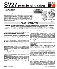
SV27 Series Sensing Valves Installation Instructions
Overview
The ROSS Controls SV27 Series is a family of premium-quality poppet sensing valves designed for inline mounting in Category 2 and Category 3 pneumatic safety applications. These valves are purpose-built for sensing pressure conditions within a pneumatic safety circuit and providing feedback to the control system through an auxiliary pressure indicator or pressure switch.
The SV27 Series includes both standard sensing valve configurations and pilot operated (PO) check sensing valve configurations (see SS281 for PO check version). The valve is designed for base mounting or inline installation and accommodates both solenoid pilot control and pressure control actuation methods. An auxiliary 1/8 NPT port connected to the outlet port (2) allows installation of an optional pressure indicator (988A30) or pressure switch kit (608A86).
Important: ROSS SV27 Series valves are not designed as control valves for air clutch/brake mechanisms on mechanical power presses and must not be installed for such use. ROSS Controls has been manufacturing fluid power products since 1921. Additional technical documentation is available at www.rosscontrols.com.
Key Features
Poppet Design for Inline Mounting
The SV27 Series uses a poppet valve design for reliable sealing and long service life. The inline mounting configuration simplifies installation in existing pneumatic circuits without the need for special bases or manifolds, making it ideal for retrofitting or upgrading existing machine safety systems.
Category 2 and 3 Safety Performance
The SV27 Series is rated for Category 2 and Category 3 applications per ISO 13849-1. Functional safety data includes: Category 2 PL d; B10D values for valve (20,000,000) and switch (2,000,000); PFHD of 2.35×10⁻⁷; MTTFd of 98.15 years (n: 7360 cycles); DC values of 99% for 3/2 valves and 90% for 2/2 and PO Check valves (obtained by monitoring safety switch status).
Auxiliary Outlet Pressure Port
An auxiliary 1/8 NPT port connected to the outlet port (2) allows installation of an optional pressure indicator (Part No. 988A30) or pressure switch kit (Part No. 608A86). This port enables pressure sensing and feedback integration without requiring additional tees or fittings in the main air line, simplifying circuit design.
Technical Specifications
- Safety Category: Category 2 PL d; Category 3
- Construction: Poppet
- Mounting Type: In-Line
- Flow Media: Filtered air
- Ambient Temperature: 40° to 120°F (4° to 50°C)
- Media Temperature: 40° to 175°F (4° to 80°C)
- Inlet Pressure: 40 to 150 psig (2.8 to 10.3 bar)
- Pilot Pressure: Must be equal to or greater than inlet pressure
- Solenoid: AC or DC power; rated for continuous duty
- Standard Voltages: 24 VDC; 110–120 VAC, 50/60 Hz
- CNOMO Style Power Consumption: 11 VA inrush, 8.5 VA holding (50/60 Hz); 6 watts DC
- Pacer Style Power Consumption: 87 VA inrush, 30 VA holding (50/60 Hz); 14 watts DC
- Switch Current/Voltage Max.: 2.5 A / 120 VAC
- Switch Current/Voltage Min.: 50 mA / 24 VDC
- Functional Safety: B10D: Valve 20,000,000; Switch 2,000,000; PFHD: 2.35×10⁻⁷; MTTFd: 98.15 years
- DC (monitoring via switch): 3/2 valves 99%; 2/2 and PO Check valves 90%
- Testing Frequency: ROSS recommends testing switch function and sealing for load holding valves every 8 hours
- Auxiliary Port: 1/8 NPT connected to outlet (Port 2) for pressure indicator or switch kit
- Application Limitation: Not for mechanical power press clutch/brake control
Applications
Pneumatic Pressure Sensing in Safety Circuits
The SV27 Series is used wherever a pneumatic safety circuit requires positive verification of pressure conditions. By sensing outlet pressure via the auxiliary port, the valve enables the machine control system to confirm that a commanded pneumatic state has been achieved — a requirement in Category 2 and Category 3 safety architectures that depend on monitoring for fault detection.
Load Holding and Pressure Verification
For load holding applications, the SV27 Series provides a simple, reliable means of verifying that a pneumatic circuit is maintaining the required pressure to hold a load safely. ROSS recommends testing the switch function and sealing for load holding valve applications every 8 hours to maintain the required safety performance level.
Safety and Compliance Standards
- ISO 13849-1 — Category 2 PL d and Category 3 compliance
- B10D: Valve — 20,000,000; Switch — 2,000,000
- PFHD: 2.35×10⁻⁷
- MTTFd: 98.15 years at 7,360 cycles per year
- Diagnostic Coverage: 3/2 valves 99%; 2/2 and PO Check valves 90%
- Not for press clutch/brake control (use double valves per local/international standards)
- Testing: 8-hour switch function and sealing test recommended for load holding applications
Installation and Setup Guide
Pre-Installation Preparation
Blow all air lines clean of contaminants before installation. Install a 5-micron rated air filter in the inlet line close to the valve. Verify that supply pressure is within the 40 to 150 psig (2.8 to 10.3 bar) range.
Inline Mounting and Port Connections
To install pipe in valve ports, engage pipe one turn, apply thread sealant (tape not recommended), then tighten. This prevents sealant from entering the valve. For parallel thread fittings, do not use sealant. Ensure the Port 1 supply line is of adequate size without restrictions.
Pilot Supply Connection
For pressure control: connect a 1/4-inch control line to the threaded port in the air cap at the top of the valve. For solenoid control: pressure is supplied internally for most valves. If designated for external pilot supply, connect a 1/8-inch pilot supply line to port X-1 in the pilot housing.
Auxiliary Pressure Port and Indicator Installation
An auxiliary 1/8 NPT port connected to the outlet (Port 2) is provided for pressure sensing. Install an optional ROSS pressure indicator (Part No. 988A30) or pressure switch kit (Part No. 608A86) in this port to sense outlet pressure. Connect pressure switch outputs to the machine control system as required.
Why Choose ROSS Controls
ROSS Controls has been manufacturing pneumatic valves for over 100 years. The SV27 Series is a proven solution for pressure sensing in pneumatic safety circuits, with comprehensive functional safety data to support ISO 13849 calculations. For application support, contact ROSS at 1-800-GET-ROSS or visit www.rosscontrols.com.
Download This Document
The official SV27 Series Sensing Valves Installation Instructions (document SS280) provides complete valve specifications, installation procedures, and service kit information.
Download PDF: https://ross-admin-global-us-east.s3.amazonaws.com/production/uploads/document_language_file/file/62/ROSS_SV27_Series_Sensing_Valves_Installation_Instruction_SS280.pdf
Related Products and Resources
- SV27 Series PO Check Sensing Valves — Pilot operated check valve version (SS281, doc 77)
- DM2® Series C — Category 3/4 double valves with inherent lockout
- L-O-X® Lockout Valves — Pneumatic energy isolation
- ROSS 55 Series Silencers — Exhaust noise reduction
- Optional Pressure Indicator: Part No. 988A30
- Optional Pressure Switch Kit: Part No. 608A86
Frequently Asked Questions
Q: What safety category does the SV27 Series achieve?
A: The SV27 Series achieves Category 2 PL d per ISO 13849-1. It is also suitable for Category 3 applications. Functional safety data: B10D Valve 20,000,000; Switch 2,000,000; PFHD 2.35×10⁻⁷; MTTFd 98.15 years.
Q: Can the SV27 Series be used for press clutch/brake control?
A: No. The SV27 Series must not be used as a control valve for air clutch/brake mechanisms on mechanical power presses. Only double valves conforming to local and international standards shall be used for press clutch/brake applications.
Q: What is the operating pressure range for the SV27 Series?
A: The SV27 Series operates with an inlet pressure of 40 to 150 psig (2.8 to 10.3 bar). Pilot pressure must be equal to or greater than inlet pressure.
Q: What accessory can be installed in the auxiliary port?
A: An optional ROSS pressure indicator (Part No. 988A30) or pressure switch kit (Part No. 608A86) can be installed in the auxiliary 1/8 NPT port to sense outlet pressure and provide feedback to the machine control system.
Q: How often should load holding valve switch function be tested?
A: ROSS recommends testing the switch function and sealing for load holding valves every 8 hours to maintain the required safety performance level per ISO 13849-1.
Q: What is the difference between the SV27 Series and the SV27 PO Check Series?
A: The standard SV27 Series is a sensing valve for inline mounting. The SV27 PO Check Series (SS281) includes pilot operated check functionality, providing additional flow control capability. See document SS281 for the PO Check version.
Q: What temperature range does the SV27 Series support?
A: Ambient temperature range: 40° to 120°F (4° to 50°C). Media temperature range: 40° to 175°F (4° to 80°C).
Q: What diagnostic coverage does the SV27 Series provide?
A: Diagnostic coverage (DC): 99% for 3/2 valves; 90% for 2/2 and PO Check valves, obtained by monitoring the safety switch status.