




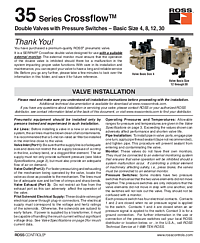
35 Series SERPAR® CrossFlow® Double Valves with Pressure Switches — Basic Sizes 4, 8, 12, and 30 Installation Instructions
Overview
The ROSS Controls 35 Series SERPAR® CrossFlow® Double Valves with Pressure Switches (Basic Sizes 4, 8, 12, and 30) are inline-mounted pneumatic press safety double valves equipped with integrated pressure switches to help detect valve element discordance. These valves are designed for use with an external monitoring system, which is required to inhibit machine operation in the event of a valve malfunction.
The CrossFlow® design passes main airflow through crossflow passages between the two valve elements, providing inherent redundancy. When both pilot solenoids are energized simultaneously, both main valve elements open and inlet air (Port 1) flows to the outlet (Port 2). When solenoids are de-energized, both elements close and downstream air exhausts through Port 3. If the valve elements do not both open or close simultaneously, the pressure switches detect this discordance and report it to the external monitor.
ROSS Controls, founded in 1921, has over 100 years of fluid power expertise. These valves support OSHA press safety requirements when used with a compliant external monitor. Visit www.rosscontrols.com or call 1-800-GET-ROSS for additional documentation and distributor information.
Key Features
Integrated Pressure Switches for Discordance Detection
Models with pressure switches include two switches — one per valve element — that detect whether both elements shifted simultaneously. Each switch has four electrical contacts: contacts 1 and 2 closed when depressurized (no signal); contacts 1 and 4 closed when pressurized. Contact 3 is ground. Voltage at the pressure switches must not exceed 250 volts. These switches provide the signal inputs needed by an external monitor to detect and respond to valve element discordance.
CrossFlow® Design for Inline Press Safety Applications
The CrossFlow® architecture ensures both valve elements must fully shift before Port 2 receives pressure. This provides a physical redundancy layer for press safety control. The inline mounting configuration suits a wide range of press control panel layouts for Basic Sizes 4, 8, 12, and 30.
Wide Solenoid Voltage Range
Standard voltages include 24 volts DC, 110–120 volts AC, and 230 volts AC at 50/60 Hz, covering the full range of press room electrical supply standards. Solenoids are rated for continuous duty.
External Monitor Compatibility
These valves are designed to interface with ROSS and third-party external monitors for press safety applications. The pressure switch outputs provide the necessary feedback signals for monitor operation. The monitor, not the valve pressure switches, provides the lockout function when discordance is detected.
Technical Specifications
The following specifications are from the 35 Series CrossFlow® Double Valves installation instructions (SS147):
- Construction: Dual poppet, inline mounting
- Pilot Solenoids: Two, rated for continuous duty
- Standard Voltages: 24 volts DC; 110–120 volts AC; 230 volts AC, 50/60 Hz
- Voltage at pressure switches: must not exceed 250 volts
- Power Consumption — Basic Size 4: 35 VA max inrush, 22 VA max holding (50/60 Hz); 14 watts nominal DC
- Power Consumption — Basic Sizes 8, 12, 30: 87 VA max inrush, 30 VA max holding (50/60 Hz); 14 watts nominal DC
- Electrical Connections: Cord-grip connectors at solenoids per EN 175301-803 Form A
- Enclosure Rating: IP65 (Basic Size 4, IEC 60529); IP65 per IEC Pub. 144 and DIN 40050 (Basic Sizes 8, 12, 30)
- Ambient Temperature: 40° to 120°F (4° to 50°C)
- Media Temperature: 40° to 175°F (4° to 80°C)
- Flow Media: Filtered compressed air (5-micron recommended)
- Inlet Pressure: 30 to 125 psig (2 to 8.5 bar)
- Pressure Switches: 2 per valve (selected models); 4 contacts each; max 250 VAC
Applications
Mechanical Press Clutch/Brake Safety Control
The 35 Series CrossFlow® valves with pressure switches are designed for press brake, mechanical power press, and shear machine safety circuits requiring externally monitored redundant valve control. The pressure switch outputs connect to the external monitor, which inhibits press cycling if valve element discordance is detected. This configuration supports compliance with OSHA 29 CFR 1910.217 for mechanical power press safety.
Industrial Machinery Pneumatic Safety Shutoff
Beyond mechanical presses, these valves suit any heavy industrial machine requiring an externally monitored pneumatic safety shutoff valve. Basic Sizes 8, 12, and 30 provide the high-flow capacity needed for large-tonnage presses and industrial machinery with significant pneumatic clutch/brake air consumption.
Safety and Compliance Standards
- OSHA 29 CFR 1910.217 — Mechanical power press safety (with external monitor)
- ISO 13849-1:2015 — Safety-related parts of control systems
- IEC 60529 / DIN 40050 — IP65 enclosure protection
- EN 175301-803 — Form A electrical connector standard
- ROSS recommended: 5-micron-rated inlet air filtration
Installation and Setup Guide
Air Line Preparation
Before installing, blow the air lines clean of all contaminants. Install a 5-micron-rated air filter in the inlet line close to the valve. Foreign material in the valve is the primary cause of premature failure and nuisance lockouts in press safety applications.
Port Connections
Valve Inlet (Port 1): Supply line must be adequately sized, free of crimps or sharp bends. The supply must provide both adequate pressure and volume on demand. Valve Outlet (Port 2): Locate the valve close to the press mechanism. Lines must be free of restrictions. Valve Exhaust (Port 3): Do not restrict exhaust — this adversely affects valve operation and can cause nuisance lockouts by the monitoring system.
Solenoid Electrical Supply
Connect pilot solenoid power via cord-grip connectors at the solenoids. The electrical supply must match solenoid voltage and frequency ratings. If a transformer supplies power, it must handle inrush current without significant voltage drop. See valve specifications for inrush current data.
External Monitor and Pressure Switch Wiring
Connect the pressure switch wiring and external monitor per the circuit diagram supplied with the valve. Contact ROSS Technical Service at 1-888-TEK-ROSS for guidance on pressure switch connection and external monitor selection.
Why Choose ROSS Controls
ROSS Controls, founded in 1921, has over 100 years of fluid power engineering expertise. The 35 Series SERPAR® and CrossFlow® product lines have proven themselves across decades of press safety applications. ROSS backs every product with global technical support and a comprehensive distributor network. Contact ROSS at 1-800-GET-ROSS or visit www.rosscontrols.com.
Download This Document
The official 35 Series CrossFlow® Double Valves installation instructions (SS147) are available as a free PDF download.
PDF Download URL: https://ross-admin-global-us-east.s3.amazonaws.com/production/uploads/document_language_file/file/55/ROSS_35_Series_Crossflow_Double_Valves_4-8-12-30_Installation_Instructions_SS147.pdf
Related Products and Resources
- 35 Series SERPAR® CrossFlow® Double Valves Installation Instructions (Basic Size 1 & 2, SS146)
- 35 Series SERPAR® Double Valves — with integral L-G, E-P, or D-S monitor
- 35 Series SERPAR® Double Valves with Dual Monitoring (CSA Z142 compliant)
- 35 Series CrossFlow™ Double Valves Operating Instructions (RC-35CF-OI)
- DM2® Series D Double Valves — self-contained Cat. 4 press safety valve
- ROSS External Monitors — for use with non-self-monitored double valves
- ROSS L-O-X® Lockout Valves — pneumatic energy isolation
- ROSS 55 Series Silencers — exhaust noise reduction
Frequently Asked Questions
Q: Do the pressure switches lock out the valve?
A: No. The pressure switches are indicators only — they detect when the two valve elements did not shift simultaneously and report this to the external monitoring system. Only the external monitor provides the lockout function that prevents further valve cycling.
Q: What is the maximum voltage allowed at the pressure switches?
A: The voltage at the pressure switches must not exceed 250 volts.
Q: What is the inlet pressure range for these valves?
A: Inlet pressure ranges from 30 to 125 psig (2 to 8.5 bar).
Q: What enclosure protection rating do these valves carry?
A: Basic Size 4 carries IP65 per IEC 60529. Basic Sizes 8, 12, and 30 carry IP65 per IEC Publication 144 and DIN 40050, Sheet 1.
Q: What standard voltages are supported?
A: 24 volts DC, 110–120 volts AC, and 230 volts AC at 50/60 Hz.
Q: How do the pressure switch contacts work?
A: Each pressure switch has four contacts. Contacts 1 and 2 are closed when no air pressure signal is applied (depressurized state). Contacts 1 and 4 are closed when an air pressure signal is applied. Contact 3 is the ground connection.
Q: Can these valves be used without an external monitor?
A: No. These valves do not have integrated monitors. They must be connected to an external monitoring system that inhibits press operation if a malfunction occurs. For self-contained monitor options, see the DM2® Series D or 35 Series SERPAR® with integral monitor.
Q: What type of pipe thread sealant should be used during installation?
A: Apply pipe thread sealant (tape is not recommended) after engaging the pipe one turn. This prevents sealant from entering and contaminating the valve. For parallel thread fittings (SAE, ISO 228-G), do not use sealant.
Q: How do I obtain service kits?
A: Service kits for valve body components, gaskets, and seals are available from ROSS Controls and authorized distributors. Contact ROSS at 1-800-GET-ROSS or visit www.rosscontrols.com.
Q: What air filtration is recommended?
A: ROSS recommends a 5-micron-rated filter in the inlet line close to the valve. Drain the filter bowl regularly. Install an automatic drain if manual draining is inconvenient.