




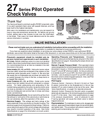
27 Series Pilot Operated Check Valves Installation Instructions
Overview
ROSS Controls, founded in 1921 with over 100 years of leadership in fluid power, offers the 27 Series Pilot Operated Check Valves as premium-quality pneumatic cylinder load-holding and trapped pressure relief devices. Available in single PO check, dual PO check, and solenoid-controlled dual PO check configurations, these poppet-construction valves are designed for inline mounting and provide directional flow control for pneumatic cylinder circuits where load holding or controlled pressure release is required.
A pilot operated check valve allows free flow in one direction (from the directional valve to the cylinder) but blocks reverse flow (from the cylinder back to the directional valve) unless a pilot signal is applied. This allows cylinders to hold loads safely even if the directional valve is de-energized. In configurations with remote trapped pressure relief, application of a signal to port P maintains normal check valve operation; loss of pressure at port P causes the check valve to relieve trapped cylinder pressure, enabling controlled load release.
For questions about installation or specifications, contact ROSS at 1-800-GET-ROSS or visit www.rosscontrols.com.
Key Features
Poppet Construction for Zero-Leakage Load Holding
The poppet internals provide a positive, zero-leakage seal in the blocked flow direction when the pilot signal is absent. This makes the 27 Series PO check valve ideal for cylinder load-holding applications where even small amounts of internal leakage could cause gradual load settling. The poppet design is also inherently more contamination-tolerant than spool-type check valve designs.
Single, Dual, and Solenoid-Controlled Configurations
Single PO check: controls one cylinder port. Dual PO check: controls both ports of a double-acting cylinder simultaneously, providing bidirectional load holding. Dual PO check solenoid controlled: adds an integral solenoid pilot to the dual PO check for electrical control of the check valve pilot signal. Valve inlet ports (V1, V2, or VLV) connect to the directional valve outlets; valve outlet ports (C1, C2, or CYL) connect to the cylinder ports.
Remote Trapped Pressure Relief Option
Valves designated for remote trapped pressure relief function (blowdown) require a 1/8-inch supply line connected to port P (or port BP). Maintaining pressure at port P provides normal check valve operation. Removing pressure from port P causes the check valve to relieve trapped cylinder pressure. This feature enables safe, controlled release of cylinder load pressure during lockout/tagout procedures, an essential requirement for machinery maintenance safety.
Technical Specifications
- Construction: Poppet
- Mounting Type: In-Line
- Ambient/Media Temperature: 40° to 175°F (4° to 80°C)
- Flow Media: Filtered air
- Pressure-Controlled PO Check (Without Trapped Pressure Relief): Inlet Pressure 15 to 150 psig (1.0 to 10.3 bar)
- Signal Pressure: Must be equal to or greater than inlet pressure
- Pilot Supply (Pressure Control): 1/8-inch control line to threaded port in air cap (VP port on some models); 1/4-inch on Type B valves
- Pilot Supply (Solenoid Control): External 1/8-inch pilot supply line to port P
- Valve Inlet Ports: V1, V2, or VLV (connect to directional valve outlets)
- Valve Outlet Ports: C1, C2, or CYL (connect to cylinder ports)
- Remote Trapped Pressure Relief Port: P or BP (1/8-inch supply line)
- Solenoid Voltage/Hertz: Per pilot housing label
- Filter Rating Recommended: 5-micron rated upstream filter
Applications
Vertical Cylinder Load Holding
Pneumatic cylinders lifting or supporting loads vertically require positive load holding when the directional valve is de-energized or in the center position. The 27 Series PO check valve traps cylinder pressure and prevents load drop even if the directional valve leaks or is de-energized. Dual PO check configurations hold loads in both the extend and retract directions, making them suitable for pneumatic lift tables, presses, and clamping fixtures.
Safe Maintenance Pressure Release
During machine maintenance under lockout/tagout, the remote trapped pressure relief option (port P or BP) provides a controlled means to safely release trapped cylinder pressure before a mechanic enters the work zone. By removing pilot supply pressure from port P, cylinder pressure is relieved through the check valve in a controlled manner rather than through sudden uncontrolled movement.
Safety and Compliance Standards
Before service, turn off electrical power, shut off air supply, exhaust all system pressure, and lock out all power sources per OSHA 1910.147 and EN 1037. Do not restrict exhaust or vent ports. Use MobilGrease 28 or equivalent for lubrication of sliding surfaces during reassembly. Install a 5-micron rated upstream filter. Solenoid voltage/hertz must match electrical supply. Loss of pressure to port P during solenoid-controlled PO check operation will cause the valve to relieve trapped pressure.
Installation and Setup Guide
Installation Steps
- Step 1: Blow air lines clean before installing the valve.
- Step 2: Install a 5-micron rated filter upstream.
- Step 3: Connect inlet port(s) (V1, V2, or VLV) to directional valve outlet(s).
- Step 4: Connect outlet port(s) (C1, C2, or CYL) to cylinder port(s).
- Step 5: Install the valve as close as possible to the cylinder for fast pressurizing and exhausting.
- Step 6: Do not restrict exhaust or vent ports.
- Step 7: For pressure-controlled: connect 1/8-inch control line to VP port in air cap.
- Step 8: For solenoid-controlled: connect external 1/8-inch pilot supply to port P; match electrical supply to solenoid rating.
- Step 9: For remote trapped pressure relief: connect 1/8-inch line to port P (or BP); maintaining pressure = normal check operation; removing pressure = trapped pressure relief.
- Step 10: Apply pipe sealant (not tape) on tapered threads; engage one turn then tighten.
Why Choose ROSS Controls
ROSS Controls, founded in 1921 with over 100 years of leadership in fluid power, provides the most comprehensive range of pilot operated check valves for industrial pneumatic cylinder applications. The 27 Series PO check valves combine ROSS's proven poppet valve technology with flexible configuration options to meet the exact requirements of each application. Contact ROSS at 1-800-GET-ROSS or www.rosscontrols.com.
Download This Document
PDF download: https://ross-admin-global-us-east.s3.amazonaws.com/production/uploads/document_language_file/file/99/ROSS_27_Series_PO_Checks_Valves_Installation_Instruction_SS161.pdf
Related Products and Resources
- 27 Series Explosion-Proof Poppet Valves (SS309)
- 21 Series Explosion-Proof Poppet Valves (SS308)
- CC4 Series Safe Cylinder Stop Double Valves
- ROSS Machine Safety Product Catalog — www.rosscontrols.com
Frequently Asked Questions
Q: What is a pilot operated check valve?
A: A PO check valve allows free flow in one direction but blocks reverse flow unless a pilot pressure signal is applied. This enables cylinders to hold loads when the directional valve is de-energized.
Q: What is the inlet pressure range?
A: For pressure-controlled PO check valves without trapped pressure relief: 15 to 150 psig (1.0 to 10.3 bar).
Q: What signal pressure is required?
A: The pilot signal pressure must be equal to or greater than the inlet pressure.
Q: What is the remote trapped pressure relief port?
A: Port P (or BP): maintaining pressure here provides normal check valve function; removing pressure causes the valve to relieve trapped cylinder pressure through a controlled blowdown.
Q: What is the temperature range?
A: 40° to 175°F (4° to 80°C) for both ambient and media.
Q: What lubricant is recommended for reassembly?
A: MobilGrease 28 or equivalent for lubrication of sliding surfaces during reassembly.
Q: What configurations are available?
A: Single PO check, dual PO check, and dual PO check solenoid controlled.
Q: Where is the valve installed in the circuit?
A: As close as possible to the cylinder. Valve inlet ports (VLV, V1, V2) connect to directional valve outlets; outlet ports (CYL, C1, C2) connect to cylinder ports.