ROSS 18 & 19 Series Valves for Air Flow Control — Installation and Operating Instructions
Overview
The ROSS® 18 Series and 19 Series Valves for Air Flow Control are precision-engineered in-line pneumatic components designed for use in compressed air circuits requiring accurate flow regulation, check function, quick cylinder reversal, or shuttle logic. All units are built to ROSS's premium quality standards for inline mounting.
The 19 Series encompasses low-profile and right-angle flow control valves, check valves, shuttle valves, and quick exhaust valves, while the 18 Series provides additional flow control configurations. ROSS Controls has been delivering fluid power solutions since 1921, and these valves represent over 100 years of engineering refinement.
This document covers installation, identification, operation of each valve type, maintenance, lubrication, and full technical specifications. Additional technical documentation is available for download at www.rosscontrols.com.
Key Features
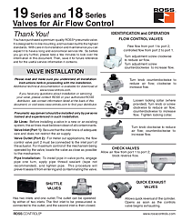
Flow Control Valves — 19 Series
Flow control valves provide free flow from Port 1 to Port 2, and controlled (metered) flow from Port 2 to Port 1. This "meter-out" configuration is standard for pneumatic cylinder speed control. Adjustment is achieved by turning the adjustment screw or knob: clockwise to reduce flow, counterclockwise to increase flow. Some models include a locking collar.
- Free flow: Port 1 to Port 2
- Controlled flow: Port 2 to Port 1 (meter-out)
- Adjustment: screw or knob (clockwise = reduce; counterclockwise = increase)
- Low-profile and right-angle configurations available
- Locking collar available on select models
Check Valves — 19 Series
Check valves allow air flow from Port 1 to Port 2 only; reverse flow is blocked. These are used to prevent back-flow and maintain pressure in circuits where directional control is required.
Shuttle Valves — 19 Series
Shuttle valves have two inlets and one outlet. The outlet can be operated by either inlet. The first inlet to be pressurized connects to the outlet, and the second inlet is then closed. This OR-logic function is used in dual-source supply circuits.
Quick Exhaust Valves — 19 Series
Quick exhaust valves allow rapid cylinder reversal by opening the exhaust path as soon as the supply valve begins exhausting, rather than routing exhaust back through the control valve. This dramatically reduces retraction time for pneumatic cylinders.
Technical Specifications
19 Series Low-Profile Flow Control Valves
- Ambient/Media temperature: 41° to 140°F (5° to 60°C)
- Flow media: Filtered air
- Supply pressure: 217 psi (14.9 bar) maximum
- Operating pressure: 150 psi (10.3 bar) maximum
19 Series Right-Angle Flow Control Valves
- Ambient/Media temperature: 40° to 175°F (4° to 80°C)
- Flow media: Filtered air
- Recommended filtration: 5-micron rated upstream filter
Maintenance and Service Notes
- Use a 5-micron rated ROSS filter upstream of the valve
- For meter-out applications, Port 2 must connect to the actuator inlet
- Exhaust silencers must have flow capacity at least equal to valve exhaust capacity
- Service kits available — see product documentation for part numbers
Applications
Pneumatic Cylinder Speed Control
Flow control valves in the 19 Series are standard for controlling the extension and retraction speed of pneumatic cylinders in machine tools, presses, assembly equipment, and packaging machinery. The meter-out configuration provides smooth, consistent motion even under varying load conditions.
Circuit Logic and Safety Functions
Check valves prevent back-pressure from affecting upstream components. Shuttle valves enable OR-logic in safety interlock circuits or dual-supply applications. Quick exhaust valves increase cylinder cycle rates in high-speed automation, improving throughput in pick-and-place, stamping, and indexing applications.
Safety and Compliance Standards
Pneumatic equipment should be installed and maintained only by persons trained and experienced in such work. All energy sources must be shut off and locked out per OSHA 1910.147 and EN 1037 before servicing. Do not restrict supply line flow or exhaust ports — restricted exhaust can cause erratic valve action and potential equipment damage.
ROSS expressly disclaims all warranties for issues caused by use of wrong type, wrong size, or inadequately maintained silencers installed with ROSS products. Use only ROSS parts for repairs.
Installation and Setup Guide
Pre-Installation Preparation
Before installing the valve, blow the air lines clean of all contaminants. Install a 5-micron rated filter upstream of the directional valve that supplies air to the flow control or check valve.
Valve Orientation and Port Connection
For meter-out applications, Port 2 must connect to the inlet port of the actuator. Locate the valve as close as possible to the actuated mechanism for maximum control response. Install pipe using thread sealant (not tape) — engage one turn, apply sealant, then tighten.
Flow Adjustment Procedure
For flow control models, adjust as follows: loosen locking collar if present; turn adjustment screw/knob clockwise to reduce flow; counterclockwise to increase flow; tighten locking collar after adjustment. For low-profile models, turn knob counterclockwise to reduce flow, clockwise to increase. Note: some models have reversed direction — confirm by observing flow change direction.
Why Choose ROSS Controls
ROSS Controls brings over 100 years of fluid power engineering expertise to every product in the 18 and 19 Series. Whether you need precise flow control, simple check logic, dual-source shuttle function, or rapid cylinder exhaust, the 18 and 19 Series valves provide reliable, long-life solutions backed by ROSS's global technical support network.
For assistance, contact ROSS at 1-800-GET-ROSS or visit www.rosscontrols.com.
Download This Document
The official PDF installation and operating instructions for the ROSS 18 & 19 Series Valves for Air Flow Control (Form SS110):
PDF Download: https://ross-admin-global-us-east.s3.amazonaws.com/production/uploads/document_language_file/file/11/ROSS_19_18_Series_Valves_for_Air_Flow_Control_Installation_Instructions_SS110.pdf
Full document library: https://www.rosscontrols.com/en/documents
Related Products and Resources
- ROSS 11 Series and 12 Series Mechanical & Manual Valves (SS105)
- ROSS 31 Series and 36 Series Manual Valves (SS104)
- ROSS RM Series Foot Pedal Valves (SS107)
- ROSS Modular Filter / Regulator / Lubricator (FRL) Systems
- ROSS L-O-X® Energy Isolation Valves
- 1-800-GET-ROSS | www.rosscontrols.com
Frequently Asked Questions
Q: What is the maximum operating pressure for the 19 Series low-profile flow control valve?
A: The maximum operating pressure is 150 psi (10.3 bar), with a supply pressure maximum of 217 psi (14.9 bar).
Q: Which port connects to the actuator for meter-out flow control?
A: For meter-out applications, Port 2 of the flow control valve must connect to the inlet port of the actuator (cylinder or other device). Free flow is from Port 1 to Port 2; controlled flow is from Port 2 to Port 1.
Q: How do I increase flow on a flow control valve?
A: Turn the adjustment knob or screw counterclockwise to increase air flow. Turn clockwise to reduce flow. For knob-type models with reversed direction, observe the flow change to confirm direction before locking.
Q: How does a shuttle valve work?
A: A shuttle valve has two inlets and one outlet. Whichever inlet is pressurized first connects to the outlet, and the other inlet is closed. This provides OR-logic: the outlet is pressurized if either of the two inlets is pressurized.
Q: When should I use a quick exhaust valve?
A: Use a quick exhaust valve when fast cylinder retraction speed is needed. The quick exhaust valve opens the exhaust path as soon as the control valve begins exhausting, bypassing the long return line to the control valve and allowing the cylinder to exhaust locally at high speed.
Q: Do the 18 and 19 Series valves require air line lubrication?
A: Air line lubrication is not required for the 18 and 19 Series valves. However, if other mechanisms in the system use a lubricator, use only compatible oils — petroleum base, ISO 32 or lighter, no phosphate additives.
Q: What filter rating is recommended upstream of these valves?
A: ROSS recommends a 5-micron rated filter installed upstream of the directional valve that supplies air to the flow control or check valve. The filter bowl should be drained regularly and fitted with an auto drain if draining is difficult.
Q: How do I clean these valves?
A: Use any good commercial solvent. Do not use chlorinated solvents (which damage seals) or abrasive materials. Do not scrape varnished surfaces. Replace worn components using ROSS service kits.