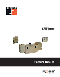
ROSS SAE Directional Control Valves Catalog: Series 80 & 84 Technical Guide
The ROSS Controls SAE Directional Control Valves catalog provides comprehensive technical specifications, dimensional data, and application guidance for the complete range of Series 80 and Series 84 pneumatic valves. These base-mounted directional control valves are engineered to conform to Society of Automotive Engineers (SAE) J2051 standards, ensuring interchangeability with SAE bases across industrial applications requiring precision pneumatic control.
This technical resource serves engineers, maintenance professionals, and procurement specialists seeking detailed information on ROSS SAE valve configurations, performance characteristics, mounting solutions, and selection criteria for automated production equipment, material handling systems, and general industrial automation applications.
What's Inside the ROSS SAE Valves Catalog
Series 80 Spool & Sleeve Valves - Technical Overview
The Series 80 represents ROSS Controls' advanced line of spool and sleeve directional control valves designed for high-cycle industrial applications. These base-mounted valves feature a micro-thin air bearing between the spool and sleeve, ensuring rapid valve response times and extended service life in demanding pneumatic systems.
Key Technical Features Covered:
- Solenoid pilot operation providing high shifting force with low power consumption
- Available in SAE sizes 125, 250, and 500 conforming to SAE J2051 specifications
- 2-position and 3-position configurations with 5-ported 4-way functionality
- Single solenoid spring return and double solenoid detented options
- Internal/external pilot capability for flexible system integration
- Sealless design eliminating wear components for extended maintenance intervals
- Operating pressure range from vacuum to 150 psig (10 bar)
- Flow coefficients (Cv) ranging from 4.0 to 8.2 depending on size
The catalog provides complete dimensional drawings showing SAE size 125 measuring 1.80 inches (45 mm) in length, SAE size 250 at 2.60 inches (65 mm), and SAE size 500 at 3.0 inches (76 mm). Width and height specifications accommodate proper mounting space allocation during system design phases.
Series 84 Poppet Valves - Construction & Performance
The Series 84 poppet valve line offers robust construction for applications requiring exceptional contamination tolerance and near-zero leakage characteristics. The poppet design eliminates sliding seals, making these valves ideal for environments with particulate contamination or extended periods between maintenance cycles.
Technical Specifications Detailed in Catalog:
- Rubber-coated aluminum and stainless steel poppet construction
- Enhanced dirt tolerance compared to sliding spool designs
- Suitable for vacuum applications when used with external pilot supply
- Available in same SAE sizes (125, 250, 500) as Series 80 for interchangeability
- Flow coefficients: SAE 125 (1.8 Cv), SAE 250 (5.7 Cv), SAE 500 (8+ Cv)
- 5/2 and 5/3 valve functions with spring return or detented center positions
- Open center, closed center, and pressure center configurations
- Continuous duty solenoid operation for 24/7 production environments
The catalog includes cross-sectional illustrations demonstrating the poppet sealing mechanism and internal pilot flow paths critical for understanding valve operation during troubleshooting or system optimization.
SAE Valve Configurations & Functions
5/2 Function Directional Control Valves
The 5-port, 2-position (5/2) valves represent the most common configuration for single-acting cylinder control and bi-directional actuator applications. The catalog details both single solenoid spring return versions and double solenoid detented models.
Single Solenoid 5/2 Valves:
Single solenoid configurations feature one electrical coil that shifts the valve when energized, with spring return to the de-energized position when power is removed. This provides fail-safe positioning for safety-critical applications. The catalog documents:
- Normally open and normally closed default positions
- Power consumption specifications: 8-14 watts for DC operation
- VA ratings for AC operation: 8 VA inrush, 6 VA holding on 50/60 Hz
- Response time data for cycle rate planning
- Exhaust flow characteristics for proper cylinder speed control
Double Solenoid 5/2 Valves:
Double solenoid models employ two independent coils for positive positioning in both directions with detented (no spring return) operation. This eliminates continuous power requirements when maintaining position, reducing heat generation and energy consumption. Technical data includes:
- Electrical connection options: 4-pin micro, 5-pin micro, and 5-pin mini connectors
- Ford, Chrysler, and generic wiring specifications
- Manual override options: non-locking push-button for emergency operation
- Pilot supply requirements for both internal and external pilot configurations
5/3 Function Three-Position Center Valves
The 5-port, 3-position (5/3) valves enable mid-stroke stopping and floating loads through various center position configurations. The catalog provides detailed flow path diagrams for each center type:
Open Center Configuration:
In the open center position, all ports connect to exhaust, allowing cylinder drift under external loading. The catalog illustrates applications including:
- Free-floating workpiece positioning systems
- Gravity-assisted material transfer operations
- Soft landing applications requiring end-of-stroke deceleration
Closed Center Configuration:
The closed center blocks all ports in the neutral position, hydraulically locking cylinders in place. Technical documentation covers:
- Holding force calculations based on valve leakage specifications
- Pressure build-up considerations during thermal expansion
- Suitable applications: vertical load holding, workpiece clamping
Pressure Center Configuration:
Pressure center directs supply pressure to both work ports while blocking exhaust, creating a cushioning effect. The catalog explains:
- Shock absorption mechanisms during mid-stroke stops
- Application sizing for proper cushioning performance
- Energy consumption during extended hold periods
Mounting Solutions & System Integration
Individual Sub-Base Mounting Systems
The catalog extensively covers individual sub-base options providing flexible mounting for standalone valve installations. Sub-base technical data includes:
Port Configuration Options:
| SAE Size | Port P (Inlet) |
Ports A & B (Work) |
Ports EA & EB (Exhaust) |
| 125 | 1/4" NPT |
1/4" NPT |
1/8" NPT |
| 250 | 1/2" NPT |
1/2" NPT |
1/4" NPT |
| 500 | 3/4" NPT |
3/4" NPT |
1/2" NPT |
Table 1: Standard Sub-Base Port Sizing
The catalog specifies mounting hole patterns, bolt torque requirements, and O-ring specifications for leak-free installation. Surface finish requirements ensure proper valve-to-base sealing without excessive torque that could distort aluminum housings.
Manifold Base Mounting for Multiple Valves
Multi-station manifold systems reduce installation time, minimize leak points, and provide centralized air distribution. The catalog documents:
Manifold System Advantages:
- Single pressure supply connection serves multiple valves
- Common exhaust collection reduces plumbing complexity
- Modular expansion accommodates production line changes
- Reduced footprint compared to individual sub-bases
- Integrated pressure monitoring ports for system diagnostics
Manifold Configuration Details:
- End station mounting specifications
- Expansion station options for system growth
- Pressure drop calculations through manifold galleries
- Maximum number of stations per manifold section
- Tie-rod specifications and installation torque values
Electrical Connection Options & Specifications
Connector Types & Wiring Standards
ROSS SAE valves accommodate multiple electrical connection standards to integrate with diverse control systems. The catalog provides pinout diagrams and wiring specifications for:
4-Pin Micro Connectors:
Compact profile for space-constrained installations, featuring:
- Ford and Chrysler wiring standard compatibility
- Current carrying capacity up to 2 amps
- Vibration-resistant latching mechanism
- IP65 environmental sealing when properly mated
5-Pin Micro Connectors:
Additional pilot supply connection for external pilot operation:
- Compatible with ISO 4400 mating connectors
- Separate ground pins for electrical noise immunity
- Color-coded wiring for simplified field troubleshooting
5-Pin Mini Connectors:
Larger contact area for heavy-duty applications:
- Enhanced current capacity for AC solenoid operation
- Rugged housing withstands industrial environments
- Quick-disconnect design reduces maintenance time
Voltage Options & Power Consumption
The catalog documents complete electrical specifications for system power supply selection:
DC Voltage Options:
- 24 VDC nominal (operational range: 19.2V to 28.8V per IEC standards)
- Power consumption: 8-14 watts depending on valve size
- Continuous duty rating for 24/7 operation
- Inrush current specifications for power supply sizing
AC Voltage Options:
- 110/120 VAC, 50/60 Hz operation
- VA ratings: 8 VA inrush, 6 VA holding for smaller sizes
- 87 VA inrush, 30 VA holding for SAE 500 sizes
- Internal rectification for universal AC compatibility
Materials of Construction & Environmental Ratings
Valve Body & Internal Components
Material selection ensures compatibility with industrial pneumatic media and environmental conditions:
Valve Body Construction:
- Cast aluminum housings provide lightweight strength
- Anodized exterior surfaces resist corrosion
- Internal passages machine-finished for minimal pressure drop
- Threaded ports comply with ANSI/ASME B1.20.1 standards
Spool/Poppet Materials:
- Series 80: Stainless steel spools resist corrosion and wear
- Series 84: Rubber-coated aluminum poppets with stainless steel guides
- Hard-anodized surfaces on wear areas extend service life
- Precision ground components ensure tight tolerances
Seal Materials & Media Compatibility
The catalog specifies seal materials and their compatibility with various pneumatic media:
Standard Buna-N Seals:
- Temperature range: -4°F to 175°F (-20°C to 80°C)
- Compatible with filtered compressed air per ISO 8573-1
- Resistant to mineral oils and hydraulic fluids
- Shore A durometer specifications for proper sealing
Optional Seal Materials:
Special seal compounds available for extreme conditions (consult catalog specifications):
- Fluorocarbon (Viton®) for high-temperature applications
- EPDM for steam and hot water compatibility
- Polyurethane for enhanced wear resistance
Performance Data & Flow Characteristics
Flow Coefficient (Cv) Values
Flow capacity sizing represents critical information for achieving desired cylinder speeds and system performance. The catalog provides Cv data for all valve configurations:
Series 80 Flow Coefficients:
| SAE Size | Average Cv |
Flow at 100 psi (SCFM) |
| 125 | 1.8 - 2.0 |
120 - 133 |
| 250 | 4.0 - 4.5 |
266 - 300 |
| 500 | 8.0 - 8.2 |
533 - 546 |
Table 2: Series 80 Spool & Sleeve Flow Performance
Series 84 Flow Coefficients:
| SAE Size | Average Cv |
Flow at 100 psi (SCFM) |
| 125 | 1.8 |
120 |
| 250 | 5.7 |
380 |
| 500 | 8+ |
533+ |
Table 3: Series 84 Poppet Flow Performance
Pressure Drop & System Efficiency
Understanding pressure drop through directional valves ensures adequate force delivery to actuators. The catalog includes:
Pressure Drop Curves:
- Graphical representations of pressure drop vs. flow rate
- Data for both flow directions (P to A, P to B)
- Exhaust port pressure drop characteristics
- Temperature compensation factors
Pilot Pressure Requirements:
- Internal pilot minimum: equal to or greater than inlet pressure
- External pilot specifications: 40-150 psig operational range
- Pilot flow consumption for power budget calculations
- Differential pressure requirements for reliable shifting
Application Guidelines & System Design
Vacuum Applications
ROSS SAE valves operate effectively in vacuum systems when properly configured. The catalog addresses:
Vacuum Operation Requirements:
- External pilot supply mandatory for vacuum service
- Minimum pilot pressure: 40 psig (3 bar) recommended
- Special exhaust port considerations for vacuum system integration
- Seal material selection for low-pressure operation
Vacuum System Applications:
- Pick-and-place material handling with vacuum grippers
- Packaging machinery vacuum-assisted product positioning
- Woodworking vacuum clamping systems
- Thermoforming machine vacuum forming operations
High-Cycle Rate Applications
ROSS spool and sleeve designs excel in high-speed automation requiring millions of cycles:
Cycle Life Data:
- Expected service life exceeding 100 million cycles
- Accelerated life test data under maximum pressure and temperature
- Maintenance interval recommendations based on operating conditions
- Wear indicators and predictive maintenance guidance
High-Speed Design Features:
- Rapid response times minimize cycle delays
- Low mass moving components reduce shifting inertia
- Optimized port geometry ensures complete exhaust evacuation
- No seal friction enables consistent high-speed performance
Dimensional Data & Installation Requirements
Overall Dimensions & Mounting Footprints
Accurate dimensional information facilitates machine design and retrofit applications. The catalog provides:
SAE Size 125 Dimensions:
- Length: 1.80 inches (45 mm)
- Width: 5.50 inches (140 mm)
- Height: 5.10 inches (129 mm)
- Weight: 2.8 - 3.3 lbs (1.3 - 1.5 kg) depending on configuration
SAE Size 250 Dimensions:
- Length: 2.60 inches (65-66 mm)
- Width: 6.40 inches (160 mm)
- Height: 5.60 inches (142 mm)
- Weight: 5.7 - 6.5 lbs (2.6 - 2.9 kg) depending on configuration
SAE Size 500 Dimensions:
- Length: 3.0 inches (76 mm)
- Width: 9.80 - 11.25 inches (248 - 286 mm) depending on function
- Height: 4.80 inches (121 mm)
- Weight: 8.3 - 9.5 lbs (3.7 - 4.3 kg) depending on configuration
Clearance Requirements & Maintenance Access
Proper installation spacing ensures serviceability and heat dissipation:
Minimum Clearances:
- Side clearance: 2 inches minimum for connector access
- Top clearance: 3 inches minimum for manual override actuation
- Front clearance: 4 inches recommended for valve removal
- Ambient air circulation requirements for continuous duty operation
Temperature Ratings & Operating Conditions
Ambient Temperature Specifications
The catalog defines environmental limits for reliable operation:
Standard Temperature Range:
- Ambient temperature: 40°F to 120°F (4°C to 50°C)
- Solenoid coil temperature rise specifications
- Derating factors for elevated ambient conditions
- Cold weather startup considerations below 32°F (0°C)
Media Temperature Specifications
Compressed air temperature affects seal life and valve performance:
Operating Media Temperature:
- Standard range: 40°F to 175°F (4°C to 80°C)
- Extended range options available (consult factory)
- Compressed air dew point recommendations
- Moisture separator requirements for temperatures below 40°F
Manual Override Options
Non-Locking Push-Button Override
Manual override capability provides emergency actuation during electrical failures:
Override Features:
- Push-button actuation requires approximately 5 lbs force
- Non-locking design returns to solenoid control upon release
- Color-coded buttons identify valve function
- Protective guards prevent accidental activation
Applications Requiring Manual Override:
- Emergency equipment shutdown procedures
- Maintenance mode operation during electrical lockout
- Troubleshooting valve and actuator operation
- Training and commissioning activities
Accessory Components & System Enhancements
Pressure Monitoring & Diagnostics
The catalog details pressure monitoring accessories for predictive maintenance:
Pressure Sensing Ports:
- Integrated 1/8" NPT pressure tap locations
- Transducer mounting specifications
- Pressure range selection guidance
- Electrical output signal types (4-20mA, 0-10VDC)
Soft-Start Modules & Flow Control
Gradual pressure build-up extends equipment life and improves safety:
EEZ-ON® Soft-Start Integration:
- Adjustable ramp-up time: 0.5 to 5 seconds
- Reduces mechanical shock on actuators and loads
- Minimizes pressure surges in distribution systems
- Integral or remote mounting configurations
Ordering Information & Part Number Structure
Model Number Decoding
Understanding ROSS part numbering accelerates specification and procurement:
Part Number Format:
Example: 8076B6331W
- 80/84 - Series designation (80 = spool/sleeve, 84 = poppet)
- 76 - SAE size code (75 = 125, 76 = 250, 77 = 500)
- B/C - Voltage designation (B = 24VDC, C = 110/120VAC)
- 6 - Construction/pilot type
- 3/4 - Function code (3 = 5/2, 4 = 5/3)
- 3/4 - Position/return type
- 1/2 - Solenoid configuration (1 = single, 2 = double)
- W/Z - Connector type (W = Ford, Z = Chrysler)
Lead Time & Availability
Standard configurations maintain inventory for rapid delivery:
Typical Lead Times:
- Stock items: 1-2 weeks for quantities up to 10 units
- Standard configurations: 3-4 weeks for production orders
- Custom modifications: 6-8 weeks depending on specifications
- Express service available for critical applications
Technical Support & Engineering Resources
Application Engineering Services
ROSS Controls provides comprehensive technical support beyond catalog specifications:
Available Engineering Services:
- Valve sizing and selection assistance
- System pressure drop calculations
- CAD models in multiple file formats (STEP, IGES, SolidWorks)
- Custom manifold design and fabrication
- On-site system audits and optimization studies
Training & Education Programs
Technical training enhances proper valve selection, installation, and maintenance:
Training Topics:
- Pneumatic system fundamentals
- Directional valve operation and troubleshooting
- Preventive maintenance best practices
- Safety standards compliance (OSHA, ANSI)
- Energy efficiency optimization
Industry Standards & Compliance
SAE J2051 Conformance
ROSS SAE valves meet Society of Automotive Engineers standards ensuring interchangeability:
SAE J2051 Requirements:
- Mounting interface dimensions and tolerances
- Port location and sizing standardization
- O-ring groove specifications
- Performance testing protocols
- Marking and identification requirements
Safety & Quality Certifications
Manufacturing quality systems ensure consistent product reliability:
Applicable Standards:
- ISO 9001 quality management system certification
- CE marking for European machinery directive compliance
- UL/CSA electrical component recognition
- RoHS compliance for restricted substances
Competitive Advantages of ROSS SAE Valves
Design Innovation & Performance Benefits
ROSS engineering delivers measurable advantages over competitive SAE valves:
Micro-Thin Air Bearing Technology:
The Series 80 spool and sleeve design creates an air bearing between components during operation:
- Eliminates metal-to-metal contact reducing wear
- Enables rapid response times under 10 milliseconds
- Maintains consistent performance over millions of cycles
- Reduces friction for lower pilot pressure requirements
Field Convertibility:
Unique design features simplify system modifications:
- Internal to external pilot conversion without disassembly
- Manual override retrofit capability
- Connector type changes using modular coil assemblies
- Center position modifications on 5/3 valves
Total Cost of Ownership
Long-term value extends beyond initial purchase price:
Lifecycle Cost Advantages:
- Extended service life reduces replacement frequency
- Minimal maintenance requirements lower labor costs
- High energy efficiency decreases compressed air consumption
- Broad inventory availability reduces emergency procurement premiums
- Backward compatibility protects equipment investment
Related ROSS Controls Product Families
Complementary Valve Series
ROSS offers extensive pneumatic valve portfolios for diverse applications:
Inline Poppet Valves (21 & 27 Series):
- Thread-mounted installation for distributed control
- 2-way and 3-way functions
- Vacuum, standard, and high-temperature variants
ISO Valves (W60, W64, W65, W66 Series):
- ISO 15407-1, 15407-2, 5599-1, and 5599-2 compliance
- Modular manifold mounting for compact installations
- Fieldbus communication interfaces
Safety Valve Systems
ROSS pioneered control reliability in safety-critical applications:
DM2 Series Double Valves:
- Redundant monitoring for Category 4, PLe safety functions
- Crossflow design prevents single-point failures
- Integrated diagnostics for predictive maintenance
Hydraulic Safety Valves (HBB Series):
- Block and bleed functionality for hydraulic systems
- D03, D05, and D07 body sizes
- Tamper-resistant construction
Frequently Asked Questions
Valve Selection & Sizing Questions
Q: How do I determine the correct SAE valve size for my application?
A: Calculate required flow using cylinder bore area, stroke length, and desired cycle time. Select valve Cv providing 20-30% margin above calculated requirement. The catalog includes sizing worksheets and examples.
Q: Can Series 80 and Series 84 valves mount on the same sub-bases?
A: Yes, both series conform to SAE J2051 mounting interfaces, allowing interchange on common sub-bases within the same SAE size.
Q: What's the difference between spool/sleeve (Series 80) and poppet (Series 84) designs?
A: Spool/sleeve valves offer faster response and higher flow but require cleaner air. Poppet valves provide better contamination tolerance and zero leakage but slightly slower response times.
H3: Installation & Maintenance Questions
Q: What level of air filtration is required?
A: ROSS recommends 40-micron filtration per ISO 8573-1 Class 4 minimum. Series 80 benefits from 25-micron filtration for optimal life. Series 84 tolerates 40-micron adequately.
Q: How often should SAE valves be serviced?
A: In properly filtered systems, SAE valves typically operate 5-10 years without service. Annual external inspection and function testing recommended. Internal service only when performance degrades.
Q: Can I convert from internal to external pilot in the field?
A: Yes, Series 80 and 84 valves support field conversion by plugging internal pilot port and connecting external pilot supply. Consult catalog for conversion kit part numbers.
Download Your Complete ROSS SAE Valves Catalog
This comprehensive technical resource provides engineers, maintenance professionals, and procurement specialists with essential information for selecting, specifying, installing, and maintaining ROSS Controls SAE directional control valves. The complete catalog contains detailed dimensional drawings, wiring diagrams, performance curves, application examples, and troubleshooting guidance not fully covered in this overview.
Download the complete ROSS SAE Directional Control Valves catalog to access:
- Full dimensional drawings with mounting hole patterns and tolerances
- Complete electrical wiring diagrams for all connector types
- Flow performance curves across full operating pressure range
- Sub-base and manifold configuration drawings
- Part number selection tables and ordering information
- Technical specifications for over 200 standard configurations
- Application notes and system design guidelines
- Maintenance procedures and troubleshooting charts
Download Complete SAE Valves Catalog
Access the full technical specification guide including dimensional drawings, performance data, and application guidelines.