




Dale CX, LT Series Solenoid Pilot Valve & Manifolds – A Model Installation Instructions (Discontinued)
Overview
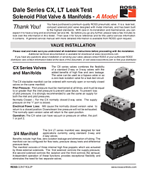
The ROSS Controls® Dale Series CX and LT Solenoid Pilot Valve Manifolds (A Model) are designed for leak test and precision pneumatic control applications. The CX series combines 2-way or 3-way flexibility with high flow, zero leakage sealing. The LT series manifolds provide complete configurable test circuit manifolds for pressure decay tests, flow tests, and differential pressure tests – all in a compact, tubing-free package replacing conventional two-valve test arrangements.
The Dale Series LT manifold integrates supply control, isolation, and exhaust in a single manifold. The 3/4 LT manifold covers basic test configurations; the 4/4 and 5/4 LT manifolds extend capability for dual supply line applications. All LT manifolds use high-flow poppet elements with zero isolation leakage, which is critical for pressure decay and differential pressure test accuracy. The supply pressure poppet is normally closed and the exhaust poppet is normally open – on power loss, supply closes and the unit under test is evacuated.
Note: Dale Series CX and LT A Model valves are discontinued. The Dale Series LT B Model is the current replacement. Contact ROSS Controls at 1-800-GET-ROSS or visit www.rosscontrols.com for replacement guidance.
Key Features
CX Zero-Leak Bidirectional Isolation Valve
The CX series valve combines zero leakage with high flow in a compact solenoid pilot valve. The CX valve supports vacuum or pressure on either port 1 or port 2, making it suitable as both a bypass valve and a zero-leak isolation valve in test circuits. CX valves are available in normally open and normally closed versions and can be mixed on the same manifold for maximum configuration flexibility.
LT Manifold for Integrated Leak Test Circuits
The Dale Series LT manifolds eliminate separate valve and tubing arrangements by integrating supply, isolation, and exhaust control in a single manifold. This eliminates tubing volume from the test circuit, improving leak test accuracy by reducing dead volume, simplifying installation, and reducing the number of potential leak points. The three-poppet design (supply, isolation, exhaust) provides independent control of each function.
Three Test Configuration Options
Dale Series LT A Model manifolds support pressure decay tests, flow tests, and differential pressure tests from a single manifold by using different port connection configurations. The 3/4 manifold provides basic test capability; the 4/4 and 5/4 manifolds add dual-supply capability for vacuum/fill, over-fill/relieve, and other complex test sequences.
Technical Specifications
The following specifications are drawn from the official ROSS Controls Dale CX, LT Series A Model Installation Instructions (Doc ID 87):
- Pilot Solenoid: DC power; rated for continuous duty
- Standard Voltages: 24 volts DC; 120 volts AC, 50 Hz
- Power Consumption per solenoid: 2.5 watts on DC; 3 VA on AC
- Ambient/Media Temperature: 40° to 120°F (4° to 50°C)
- Flow Media: Filtered air; 5-micron recommended; consult ROSS for liquid applications
- Sensor Ports: 1/8 NPT
- Pilot Pressure: 50 to 145 psi (3.4 to 10 bar); must equal or exceed inlet pressure
- Inlet Pressure: 2 to 145 psi (0.13 to 10 bar)
- Port Threads: NPT, BSPP
- LT Manifold Configurations: 3/4, 4/4, and 5/4
- LT Supply Poppet: Normally closed
- LT Exhaust Poppet: Normally open
- CX Operation: Bidirectional (vacuum or pressure on port 1 or 2)
- CX Versions: Normally open (NO) and normally closed (NC) on same manifold
- Lubricant: Dow Corning BR2-Plus for sliding surfaces
Applications
Pressure Decay, Flow, and Differential Pressure Testing
The Dale Series LT A Model manifolds support the three most common pneumatic component test methods from a single manifold. Pressure decay test: close exhaust, fill test part, isolate, close inlet, exhaust valve cavity, monitor pressure drop at P3. Flow test: fill and isolate, monitor flow between P2 and P3 using a flow sensor. Differential pressure test: monitor pressure difference between P2 and P3 after isolation to detect leak-by.
Zero-Leak Pneumatic Isolation Applications
The CX zero-leak isolation valve is used where positive shutoff with no measurable leakage is required: leak test circuit isolation, pneumatic logic circuits with strict leakage budgets, and high-precision pressure control systems. The CX valve's bidirectional capability makes it flexible for reversing circuit applications.
Safety and Compliance Standards
Dale Series CX and LT valves must be installed and maintained by trained pneumatic equipment personnel. Pilot pressure must be maintained at all times during operation and must equal or exceed inlet pressure. To prevent loss of pilot pressure, use the same air supply for both inlet and pilot pressures. If power is lost during LT valve operation, supply closes and downstream test pressure exhausts – this is designed safe-state behavior.
Installation and Setup Guide
Pressure Decay Test Operation (LT Series, 3/4 Manifold)
Step 1: Close exhaust by actuating exhaust solenoid. Step 2: Open inlet pressure by actuating fill solenoid. Step 3: Allow time to fill and settle. Step 4: Close isolation poppet by actuating isolation solenoid. Step 5: Close inlet by deactivating fill solenoid. Step 6: Exhaust valve cavity pressure by deactivating exhaust solenoid. Step 7: Monitor pressure drop on port P3 to determine if there is a leak. Step 8: Exhaust part under test by deactivating isolation solenoid.
Port Configuration for Test Types
Pressure decay test (3/4 manifold): P1 – Blocked; P2 – Blocked; P3 – Pressure Sensor Port. Flow test: P1 – Blocked; P2 – Flow Sensor Inlet Port; P3 – Flow Sensor Outlet Port. Differential pressure test: P1 – Reference Volume Fill Port; P2 – Pressure Sensor Port 1; P3 – Pressure Sensor Port 2. For 4/4 and 5/4 manifolds with dual-pressure tests: P1 – Pressure Sensor Port.
CX Valve Normal and Power Loss States
The CX normally closed 2-way valve keeps port 1 supply pressure closed in the de-energized state. On power loss, the NC valve returns to closed – downstream line pressure is NOT exhausted (unlike the LT valve which exhausts on power loss). The normally open CX valve returns to open on power loss. When mixing NC and NO valves on the same CX manifold, verify the safe-state behavior is appropriate for the application.
Why Choose ROSS Controls
ROSS Controls has over 100 years of precision valve engineering experience. The Dale Series CX and LT manifolds demonstrate ROSS's application-specific design approach, delivering integrated test circuit solutions that eliminate components, reduce installation complexity, and improve test accuracy through zero-leakage isolation. For current B Model replacements, contact ROSS at 1-800-GET-ROSS or visit www.rosscontrols.com.
Download This Document
The official ROSS Controls Dale CX, LT Series A Model Installation Instructions (Doc ID 87) can be downloaded from the ROSS Controls document library.
PDF Download URL: https://ross-admin-global-us-east.s3.amazonaws.com/production/uploads/document_language_file/file/87/ROSS_Dale_Series_LT_Valves_A-Model_Installation_Instructions_SS051_A_Model.pdf
Related Products and Resources
- Dale LT Series B Model – Current replacement Leak Tight and Leak Test manifolds (Doc ID 77)
- Dale CP, CX, LF, LX Series A Model – Standard inline poppet valves A Model (Doc ID 80)
- Dale CP, CX, LF, LX Series B Model – Current inline poppet valves (Doc ID 75)
- 21 Series Poppet Valves – Inline poppet valves for high-flow applications
- ROSS Controls Technical Documentation – www.rosscontrols.com
Frequently Asked Questions
Q: What is the key advantage of the LT manifold over two separate valves?
A: The LT manifold integrates supply, isolation, and exhaust control in a single compact unit, eliminating all tubing between separate valves. This eliminates tubing volume from the test circuit, improves leak test accuracy by reducing dead volume, simplifies installation, and reduces potential leak points.
Q: What test types can the Dale LT manifold support?
A: The Dale LT manifold supports pressure decay tests, flow tests, and differential pressure tests depending on port configuration. The 3/4 manifold supports single-supply tests; the 4/4 and 5/4 manifolds support dual-supply tests including vacuum/fill and over-fill/relieve sequences.
Q: What happens to the LT manifold when electrical power is lost?
A: The LT supply poppet is normally closed and exhaust poppet is normally open. On power loss, supply closes and downstream test pressure exhausts to atmosphere. This designed safe-state behavior protects the unit under test and prevents residual pressure hazards.
Q: Can the CX valve handle vacuum or pressure on either port?
A: Yes. The CX valve supports vacuum or pressure on either port 1 or port 2, making it bidirectional. This allows the CX to function as both a supply isolation valve and a bypass valve within the same test circuit.
Q: What is the pilot pressure requirement for Dale CX and LT A Model valves?
A: Pilot pressure must be 50 to 145 psi (3.4 to 10 bar) and must equal or exceed inlet pressure at all times. Using the same air supply for both inlet and pilot pressures is strongly recommended.
Q: What is the inlet pressure range for the Dale LT A Model?
A: The Dale LT A Model supports an inlet pressure range of 2 to 145 psi (0.13 to 10 bar). Sensor ports use 1/8 NPT thread.
Q: Is the Dale CX, LT Series A Model still available?
A: Dale Series CX and LT A Model valves are discontinued. The current replacement is the Dale Series LT B Model (Doc ID 77). Contact ROSS Controls at 1-800-GET-ROSS or www.rosscontrols.com for current availability.
Q: What sensor ports are available on the Dale LT A Model?
A: The Dale LT A Model manifolds include 1/8 NPT sensor ports. Port P3 is the primary pressure sensor for pressure decay tests; P2 is the flow sensor inlet for flow tests; P1 serves as the reference volume fill port or second pressure sensor for differential pressure tests.