




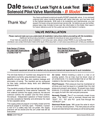
Dale Series LT Leak Tight & Leak Test Solenoid Pilot Valve Manifolds B Model – Installation & Operating Instructions
Overview
The ROSS Controls® Dale Series LT B Model is a compact solenoid pilot valve manifold designed with metal internals for precision leak tight and leak test applications. Manufactured by ROSS Controls – with over 100 years of fluid power expertise since its founding in 1921 – the Dale LT Series provides the high flow, zero isolation leakage, and application flexibility required in sophisticated test systems.
The LT Series is available in two variants: LT32NB27500**01 for leak tight applications (inlet pressure vacuum to 250 psi, pilot pressure 70 to 145 psi) and LT32NB27500** for leak test applications (inlet pressure 2 to 145 psi, pilot pressure 50 to 145 psi). The manifold was designed for applications currently using standard 3-way valves, with benefits including high flow, zero isolation leakage, and elimination of tubing through its integrated manifold design.
The supply pressure poppet is normally closed and the exhaust poppet is normally open. Therefore, if power is lost or a safety stop cuts power, the supply pressure will be closed and the unit under test will be evacuated – providing inherent fail-safe behavior. Contact ROSS at 1-800-GET-ROSS or www.rosscontrols.com.
Key Features
Three-Poppet Integrated Manifold Design
The Dale LT manifold integrates three internal high-flow poppets actuated by three external solenoids: one solenoid controls supply pressure, one controls isolation, and one controls exhaust. Independent operation of these three functions provides exceptional flexibility, enabling pressure decay tests, flow tests, and differential pressure tests from a single manifold without additional external valves.
Zero Isolation Leakage for Precision Test Applications
The zero isolation leakage design of the Dale LT Series ensures that the isolation poppet creates a complete air-tight seal when actuated. This characteristic is critical in precision pressure decay and leak test applications where even very small internal leakage would create false test failures or mask actual product leaks, particularly in high-sensitivity test applications.
Fail-Safe Normally Closed Supply and Normally Open Exhaust
The LT Series is a normally closed 4-way valve with the INLET port normally closed and the TEST, P1, P2, and P3 ports flowing through the EXHAUST port in the de-energized state. On power loss or safety stop, supply is closed and test pressure is exhausted – providing inherent fail-safe protection for both the test fixture and the part under test.
Configurable for Multiple Test Types
The Dale LT manifold supports three primary test configurations: Pressure Decay Test (P1 blocked, P2 blocked, P3 is pressure sensor port), Flow Test (P1 blocked, P2 is flow sensor inlet, P3 is flow sensor outlet), and Differential Pressure Test (P1 is reference volume fill, P2 is pressure sensor port 1, P3 is pressure sensor port 2). This configurability makes the LT Series a versatile test platform.
Technical Specifications
The following specifications are from the official ROSS Controls Dale LT Series B Model Installation Instructions (Doc ID 77, SS051 B Model):
- Construction: Poppet
- Mounting Type: Inline
- Pilot Solenoid: DC power. Rated for continuous duty
- --- Leak Tight Variant (LT32NB27500**01) ---
- Voltage/Power: 24 VDC: 1.2 watts; 110 VAC 50 Hz: 5.4 VA; 120 VAC 60 Hz: 5.0 VA (each solenoid)
- Ambient/Media Temperature: 40° to 120°F (4° to 50°C)
- Flow Media: Filtered air (for liquid applications, consult ROSS)
- Pilot Port: 1/8 NPT or G1/8
- Inlet Pressure: Vacuum to 250 psi (vacuum to 17.2 bar)
- Pilot Pressure: 70 to 145 psi (4.8 to 17.2 bar)
- --- Leak Test Variant (LT32NB27500**) ---
- Voltage/Power: 24 VDC: 1.2 watts; 110 VAC 50 Hz: 5.4 VA; 120 VAC 60 Hz: 5.0 VA (each solenoid)
- Ambient/Media Temperature: 40° to 120°F (4° to 50°C)
- Flow Media: Filtered air (for liquid applications, consult ROSS)
- Pilot Port: 1/8 NPT or G1/8
- Inlet Pressure: 2 to 145 psi (0.13 to 10 bar)
- Pilot Pressure: 50 to 145 psi (3.4 to 10 bar); must be equal to or greater than inlet pressure
Applications
Automotive Component Leak Testing
The Dale LT Series is widely used in automotive component leak testing for engine blocks, cylinder heads, oil pans, intake manifolds, and transmission housings. The zero isolation leakage and high-sensitivity pressure decay capability enable detection of very small leaks that would fail quality standards in critical drivetrain and powertrain components.
Medical Device and Precision Industrial Testing
In medical device manufacturing, the Dale LT Series supports pressure decay and flow tests on components such as IV bags, infusion pumps, blood pressure cuffs, and respiratory devices. The fail-safe normally closed supply design provides an additional layer of protection for sensitive components during test operations.
Safety and Compliance Standards
Pilot pressure must be maintained at all times and must be equal to or greater than inlet pressure to prevent valve failure. To prevent pilot pressure loss, it is strongly recommended to use the same air supply for both inlet and pilot. On power loss, the valve returns to normally closed position, closing inlet pressure and exhausting downstream test pressure.
Installation and Setup Guide
Test System Configuration
Configure the LT manifold ports according to the desired test type. For Pressure Decay: P1 blocked, P2 blocked, P3 to pressure sensor. For Flow Test: P1 blocked, P2 to flow sensor inlet, P3 to flow sensor outlet. For Differential Pressure: P1 to reference volume fill, P2 to pressure sensor port 1, P3 to pressure sensor port 2.
Pressure Decay Test Procedure
Step 1: Close exhaust by actuating exhaust solenoid. Step 2: Open inlet pressure by actuating fill solenoid. Step 3: Allow time to fill and settle. Step 4: Close isolation poppet by actuating isolation solenoid. Step 5: Close inlet by deactivating fill solenoid. Step 6: Exhaust valve cavity by deactivating exhaust solenoid. Step 7: Monitor pressure drop on port P3. Step 8: Exhaust part under test by deactivating isolation solenoid.
Pilot Pressure Management
Pilot pressure must be maintained at all times. Failure to maintain adequate pilot pressure can result in valve failure or unstable test results. Use the same air supply for both inlet and pilot to prevent pressure differentials. For leak tight models, pilot pressure must be 70 to 145 psi; for leak test models, pilot pressure must be 50 to 145 psi.
Why Choose ROSS Controls
ROSS Controls provides over 100 years of precision fluid power engineering. The Dale LT Series B Model demonstrates ROSS's capability to design highly specialized manifold valves for demanding test applications. Zero isolation leakage, fail-safe design, and multi-test configurability set the LT Series apart from standard 3-way valve alternatives.
Contact ROSS at 1-800-GET-ROSS or www.rosscontrols.com.
Download This Document
The official ROSS Controls Dale LT Series B Model Installation Instructions (Doc ID 77, SS051 B Model) can be downloaded from the ROSS Controls document library.
PDF Download URL: https://ross-admin-global-us-east.s3.amazonaws.com/production/uploads/document_language_file/file/77/ROSS_Dale_Series_LT_Valves_Model-B_Installation_Instructions_SS051_B_Model.pdf
Related Products and Resources
- Dale CX Series B Model – Zero-leakage CX isolation valve for test circuits
- Dale CX/LT Series A Model – Earlier A Model documentation reference
- Dale CP/CX/LF/LX Series B Model – Full Dale B Model directional valve range
- ROSS Pressure Regulators – Air preparation for precise test pressure control
- ROSS Service Kits – Replacement components for Dale LT Series
Frequently Asked Questions
Q: What is the difference between the Leak Tight and Leak Test LT variants?
A: The Leak Tight variant (LT32NB27500**01) supports inlet pressures from vacuum to 250 psi with pilot pressure 70 to 145 psi. The Leak Test variant (LT32NB27500**) supports inlet pressures 2 to 145 psi with pilot pressure 50 to 145 psi. Choose the variant based on your test pressure requirements.
Q: What happens to the LT Series valve on power loss?
A: On power loss or safety stop, the supply pressure is closed (normally closed supply poppet) and downstream test pressure is exhausted (normally open exhaust poppet). This fail-safe behavior protects the test fixture and part under test.
Q: What test types can the Dale LT manifold support?
A: The Dale LT manifold supports Pressure Decay Tests, Flow Tests, and Differential Pressure Tests through different port configurations. The three-solenoid design allows independent control of fill, isolation, and exhaust functions.
Q: What is the solenoid power consumption of the Dale LT Series?
A: Each solenoid consumes 1.2 watts on 24 VDC, 5.4 VA on 110 VAC 50 Hz, and 5.0 VA on 120 VAC 60 Hz. Three solenoids are present in each LT manifold assembly.
Q: What pilot pressure is required for the Leak Tight LT variant?
A: Pilot pressure for the Leak Tight variant (LT32NB27500**01) must be 70 to 145 psi (4.8 to 17.2 bar). For the Leak Test variant, pilot pressure must be 50 to 145 psi (3.4 to 10 bar). Pilot pressure must always be equal to or greater than inlet pressure.
Q: How is the Dale LT manifold connected for a Flow Test?
A: For a flow test: P1 blocked, P2 connected to flow sensor inlet, P3 connected to flow sensor outlet. Follow steps 1 through 4 of the pressure decay procedure to fill and settle, then monitor flow from P2 to P3 while the isolation poppet is closed.
Q: What is the ambient temperature range for Dale LT Series valves?
A: Ambient and media temperature is 40° to 120°F (4° to 50°C) for both LT variants. For liquid applications, consult ROSS Controls before using.
Q: Can the Dale LT Series be used with liquid media?
A: The standard media is filtered air. For liquid applications, consult ROSS Controls. The standard valve materials and seals are specified for air service; liquid compatibility must be verified by ROSS before use.