




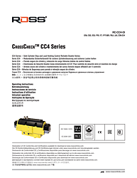
CrossCheck™ CC4 Series Safe Cylinder Stop and Load Holding Double Valves Operating Instructions
Overview
ROSS Controls, founded in 1921 with over 100 years of leadership in fluid power, offers the CrossCheck™ CC4 Series as a revolutionary category of control-reliable double valves specifically designed for safe cylinder stop and load holding applications. Unlike conventional double valves that control flow in or out, the CC4 Series uses a redundant 4-ported, 3-position closed-center (4/3) architecture that enables both safe cylinder stop and bidirectional cylinder control with a single valve assembly. This design eliminates the need for separate cylinder stop and direction control valves in many safety applications.
The CC4 Series achieves Category 4, Performance Level e (ISO 13849-1:2015) and SIL 3 (IEC 62061:2001), pending DGUV certification. The valve features four solenoids in a dual-redundant configuration (12A, 12B for one direction; 14A, 14B for the other), enabling double-solenoid directional control with inherent cross-channel monitoring. Integrated trapped pressure release buttons (one per outlet port) provide safe, manual release of cylinder trapped pressure after stopping and before maintenance work begins.
The CC4 is also available in Portuguese, Spanish, French, Italian, German, Russian, Japanese, and Chinese, reflecting its global deployment. For support, call 1-800-GET-ROSS or visit www.rosscontrols.com.
Key Features
4/3 Closed-Center Architecture for Safe Cylinder Stop
The CC4 uses a 4/3 (four-port, three-position) closed-center valve architecture. When all solenoids are de-energized, the CC4 returns to the center position, closing all ports. This stops cylinder motion by trapping air on both sides of the cylinder simultaneously, providing controlled safe stop rather than uncontrolled coast-to-stop. The closed-center design also enables jogging: briefly applying solenoids 12A and 12B (or 14A and 14B) then de-energizing returns the valve to center and stops the cylinder at a precise position.
Integrated Trapped Pressure Release System
After stopping a cylinder and completing lockout/tagout, trapped pressure can be released safely using the integrated manual trapped pressure release buttons — one per valve outlet port. These buttons provide a controlled release of trapped cylinder pressure without requiring removal of any pipe connections. WARNING: Actuating the manual trapped pressure release button will cause cylinder motion, which can result in injury or death due to sudden pressure release. Only operate the trapped pressure release after the load is supported by mechanical means and all personnel are clear of the work zone.
Redundant Poppet Valve Internals with Magnetic Position Monitoring
The CC4 is constructed with redundant, poppet-type valve internals. Each single valve within the CC4 Series is equipped with a magnetic position sensor. Monitoring both sensors on each actuation and de-actuation provides the verification required for Category 4 PL e safety performance. The machine's safety control system must de-energize all valve solenoids in the event of a fault. When a fault is detected, valve reset is accomplished by de-energizing all solenoids.
Technical Specifications
- Valve Type: CrossCheck™ CC4 Series — Control Reliable Double Valves
- Valve Architecture: Redundant 4/3 closed-center directional control
- Safety Performance: Category 4, Performance Level e (ISO 13849-1:2015)
- Safety Integrity Level: SIL 3 (IEC 62061:2001)
- DGUV Certification: Pending (HSM XXXXX)
- Solenoid Configuration: Four solenoids — 12A, 12B (one direction), 14A, 14B (other direction)
- Valve Internals: Redundant poppet type with magnetic position sensor per valve element
- Integrated Trapped Pressure Release: Manual buttons, one per outlet port
- Safety Function: Safe cylinder stop, safe cylinder control, safe load holding
- Monitoring: External monitoring required; dual-channel output from safety relay or safety PLC
- External Monitoring Output: Typically dual-channel from safety relay or safety PLC
- Applicable Standards: ISO 13849-1:2015; IEC 62061:2001
- IMPORTANT: CC4 cannot prevent loss of pneumatic energy (compressed air supply failure)
- Available Languages in Manual: English, German, Spanish, French, Italian, Portuguese, Russian, Japanese, Chinese
Applications
Safe Cylinder Stop for Ergonomic and Maintenance Tasks
Industrial applications requiring operators or maintenance personnel to work near or on machinery powered by pneumatic cylinders — including forming presses, robotic end-of-arm tooling, pneumatic clamps, lifters, and conveyors — benefit from the CC4's ability to stop the cylinder positively and hold it stopped without mechanical brakes. The closed-center 4/3 architecture traps air on both sides of the cylinder piston, providing a pneumatic cylinder lock that holds position against gravity or process loads.
Load Holding and Jogging Control
The CC4 enables precise jogging control of pneumatic cylinders — brief energization of solenoid pairs extends or retracts the cylinder incrementally, then the valve returns to center and holds the cylinder position. This functionality is valuable for setup, adjustment, and manual positioning operations on automated machinery, where the operator needs to inch a cylinder to a specific position without activating the full machine cycle.
Safety and Compliance Standards
RISK OF INJURY: Actuating the manual trapped pressure release button will cause cylinder motion. Only operate after load is mechanically supported and all personnel are clear. The CC4 Series requires external monitoring — connect to a dual-channel safety relay or safety PLC output. The CC4 cannot prevent loss of pneumatic energy from supply failures. Maintain compressed air quality (filtration, pressure regulation, lubrication). Do not plug the valve exhaust port. Use only high-flow, non-clogging silencers with similar or higher specifications as required by the application.
Installation and Setup Guide
CC4 Installation Key Points
- Step 1: Connect all four solenoids (12A, 12B, 14A, 14B) to the dual-channel safety relay or safety PLC per the machine safety design.
- Step 2: Mount the valve per the dimensional data in the operating instructions.
- Step 3: Connect inlet (Port 1) and both outlet ports to the cylinder.
- Step 4: Do not plug exhaust ports; use high-flow silencers if noise reduction is required.
- Step 5: Connect magnetic position sensor outputs to the safety monitoring system.
- Step 6: Verify that the safety control system de-energizes all solenoids on fault detection.
- Step 7: Confirm valve returns to closed center (all ports blocked) when all solenoids are de-energized.
- Step 8: Test trapped pressure release function — only with load mechanically supported and personnel clear.
- Step 9: Document all safety function validation in machine technical file.
Why Choose ROSS Controls
ROSS Controls, founded in 1921 with over 100 years of leadership in fluid power, pioneered the CrossCheck™ CC4 Series as an industry-first safe cylinder stop and load holding solution, addressing a gap in pneumatic safety valve technology that previously required multiple separate components. The CC4 integrates safe stop, direction control, and trapped pressure release in one compact package. Contact ROSS at 1-800-GET-ROSS or www.rosscontrols.com.
Download This Document
PDF download: https://ross-admin-global-us-east.s3.amazonaws.com/production/uploads/document_language_file/file/211/ROSS_CC4_Double_Valves_Operating_Instructions_RC-CC4-OI.pdf
Related Products and Resources
- 77 Series CROSSMIRROR® Double Valves
- CM26 Series CrossMirror® Double Valves
- DM2® Series C Explosion Proof Double Valves
- 27 Series PO Check Valves for Load Holding
- ROSS Machine Safety Product Catalog — www.rosscontrols.com
Frequently Asked Questions
Q: What is the CC4 valve's primary safety function?
A: Safe cylinder stop, safe cylinder control, and safe load holding. The 4/3 closed-center architecture stops the cylinder by closing all ports when all solenoids are de-energized, trapping air on both sides of the cylinder piston.
Q: How many solenoids does the CC4 have?
A: Four solenoids in a redundant configuration: 12A and 12B (for one flow direction), 14A and 14B (for the other flow direction).
Q: What is the safety performance rating?
A: Category 4, Performance Level e (ISO 13849-1:2015) and SIL 3 (IEC 62061:2001).
Q: Does the CC4 require external monitoring?
A: Yes. The CC4 requires external monitoring from a dual-channel safety relay or safety PLC. Internal monitoring data from the magnetic position sensors must be evaluated by the external safety system.
Q: What is the trapped pressure release feature?
A: Integrated manual buttons (one per outlet port) allow safe release of trapped cylinder pressure after stopping and during lockout/tagout. WARNING: Actuating these buttons causes cylinder motion — only operate with load supported and personnel clear.
Q: Can the CC4 prevent loss of cylinder control if air supply fails?
A: No. The CC4 cannot prevent loss of pneumatic energy from compressed air supply failure. The safety system must account for this failure mode.
Q: What valve architecture does the CC4 use?
A: 4/3 closed-center (four-port, three-position) with redundant poppet internals and magnetic position sensors.
Q: What languages is the CC4 operating manual available in?
A: English, German, Spanish, French, Italian, Portuguese, Russian, Japanese, and Chinese.