




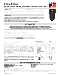
ROSS Controls High-Capacity Inline Filters: Installation & Operating Instructions
Overview
The ROSS Controls High-Capacity Inline Filter Series is engineered for demanding compressed air systems requiring port sizes from 1-1/4 through 2 NPT and flow rates up to 1,000 scfm. Designed and built in the USA by ROSS Controls—a leader in fluid power solutions since 1921—these filters protect downstream equipment from particulate contamination and moisture accumulation that can damage valves, actuators, and pneumatic tools.
ROSS High-Capacity Filters are available with float drain or manual drain configurations. The float drain model provides automatic liquid removal without operator intervention, while the manual drain model allows zero-pressure installation and is suited for dry-air environments. Both variants accept 40-micron or 5-micron sintered bronze elements to match filtration requirements.
Constructed with aluminum heads and bowls, these filters withstand continuous industrial operation across a wide ambient temperature range. Replacement parts—including bowl assemblies, filter elements, and seal kits—are stocked and available from ROSS and authorized distributors, ensuring minimal downtime during scheduled maintenance intervals.
Key Features
High Flow Capacity to 1000 scfm
Port sizes of 1-1/4, 1-1/2, and 2 NPT accommodate very high volumetric airflow requirements. At rated conditions the filter series delivers up to 1,000 standard cubic feet per minute, making it suitable for central compressor rooms, large manifolds, and high-cycle production lines where inadequate filtration creates system inefficiency.
Dual Drain Options: Float and Manual
The float drain variant automatically expels accumulated liquids through a 3/16-inch flexible tubing connection pushed onto the Drain Stem; a tube clamp retains the tubing securely. Manual drain models use a Draincock Knob turned clockwise to drain, returning the knob fully counter-clockwise for normal operation. Both options are serviceable without removing the filter from the pipeline.
Sintered Bronze Filter Elements: 40-Micron or 5-Micron Rated
ROSS offers sintered or fiber element construction. The 40-micron rated element (Part No. 944K77) handles general particulate filtration in most plant air systems. The 5-micron (0.5-micron) rated element (Part No. 942K77) provides finer filtration for sensitive instrumentation and precision pneumatic circuits. Elements must be replaced when the pressure differential reaches 8 psid—cleaning is not effective and must not be attempted.
Technical Specifications
The following specifications are extracted directly from the official ROSS product documentation (Document SS-F009):
- Construction: Sintered or fiber element
- Ambient/Media Temperature: 40°F to 175°F (4°C to 80°C)
- Fluid Media: Compressed air
- Inlet Pressure (Float Drain): 30 to 200 psig (2.1 to 14 bar)
- Inlet Pressure (Manual Drain): 0 to 200 psig (0 to 14 bar)
- Filter Element: 40-micron rated or 5-micron (0.5-µm) rated sintered bronze
- Body: Aluminum
- Bowl: Aluminum (metal)
- Seals: Nitrile
- Port Sizes: 1-1/4, 1-1/2, and 2 NPT
- Maximum Flow: 1,000 scfm
- Element Replacement Trigger: 8 psid differential pressure
- Torque – Drain Nut: 35 to 45 in-lbs
- Torque – Bowl to Head: 90 to 110 ft-lbs
- Replacement Element (0.5-µm): Part No. 942K77
- Replacement Element (40-µm): Part No. 944K77
- Float Drain Kit: Part No. R-A802-49
- Manual Drain Cock: Part No. R-103-51SP
- Seal Kit (Upper & Lower Baffle, Gasket, Bowl O-ring, Wing Nut): Part No. R-A106-19P
Applications
Central Compressed Air Systems and Distribution Headers
In large manufacturing facilities, a central compressor supplies air through main distribution headers to numerous workstations and machines. Installing ROSS High-Capacity Filters on these headers—upstream of branch takeoffs—removes bulk contaminants before air reaches critical actuators, solenoid valves, and process equipment. The 2 NPT port size enables direct inline installation without flow-reducing reducers.
Automotive and Heavy-Duty Assembly Lines
High-volume automotive assembly plants operate pneumatic torque tools, lifts, and clamps at sustained flow rates that exceed the capacity of smaller filter units. The 1,000 scfm flow rating of this series supports parallel or series filter arrangements for tool-room supply drops and robotic workcell air prep panels. Clean, dry air maintains consistent torque output and extends tool life significantly.
Safety and Compliance Standards
ROSS Controls High-Capacity Filters are designed and manufactured in compliance with applicable OSHA machine-guarding regulations and industry-standard pneumatic safety practices. Always depressurize and lock out air pressure before any installation, service, or element replacement activity. Verify the air supply is fully isolated and vented before loosening any fittings or bowl assemblies.
Polycarbonate bowls must not be used with fluids other than compressed air. Certain compressor oils, chemical cleaners, solvents, and fumes will attack polycarbonate material. Where chemical exposure is a risk, specify metal bowl assemblies (Part No. R-ABF6A106-48M for float drain, R-ABF106-48M for manual drain). A metal bowl guard must always be used when polycarbonate bowls are fitted.
- OSHA 29 CFR 1910.147 – Control of Hazardous Energy (Lockout/Tagout)
- ISO 8573 – Compressed Air Quality Standards (reference for element selection)
- ANSI/NFPA T3.21.3 – Pneumatic Fluid Power Component Standard
- Lubrication note: Use ISO 32 or lighter petroleum-base oils with aniline point 180°F–220°F; avoid phosphate-type additives (e.g., zinc dithiophosphate)
Installation and Setup Guide
Follow this sequence for safe and correct installation of the ROSS High-Capacity Inline Filter:
- 1. Depressurize and lock out air pressure before beginning any work.
- 2. Verify that upstream pipes are free of excessive dirt and liquid accumulation.
- 3. Install the Filter as close as possible to the device it is to serve.
- 4. Mount the Filter so that air flows from inlet to outlet as indicated on the head (observe the flow arrow).
- 5. The Filter MUST be installed vertically with the drain mechanism at the bottom.
- 6. Install Filters upstream of any Regulators or Lubricators in the air line.
- 7. For float drain: push 3/16-inch flexible tubing onto the Drain Stem; secure with a tube clamp. Route tubing to a holding can or vessel.
- 8. For manual drain: install the drain cock and tighten to specified torque.
- 9. After installation, gradually restore air pressure and verify there are no leaks at connections.
- 10. Monitor differential pressure; replace element when 8 psid differential is reached.
Why Choose ROSS Controls
Founded in 1921, ROSS Controls has more than 100 years of engineering expertise in fluid power—valves, regulators, filters, lubricators, and safety controls. ROSS products are manufactured to strict quality standards and supported by a global network of authorized distributors. The company's commitment to innovation and reliability has made ROSS a trusted partner in industrial automation, automotive, food processing, semiconductor, and general manufacturing sectors.
ROSS backs every product with responsive technical support. Contact ROSS at 1-800-GET-ROSS or visit www.rosscontrols.com to locate your nearest distributor, request replacement parts, or obtain application engineering assistance.
Download This Document
The official ROSS Controls Installation and Operating Instructions for the High-Capacity Inline Filter Series (SS-F009, Document ID 164) is available as a PDF download:
PDF URL: https://ross-admin-global-us-east.s3.amazonaws.com/production/uploads/document_language_file/file/164/ROSS_Filter_Inline_High-Capacity_1000_scfm_SS-F009.pdf
Related Products and Resources
- ROSS Inline Regulators – High-Capacity Series (SS-R007) for downstream pressure control
- ROSS Inline Lubricators – High-Capacity Series for downstream tool lubrication
- ROSS Modular (MD3/MD4) Filter Series for modular panel-mount air prep systems
- ROSS Silencers-Reclassifiers for exhaust noise reduction (SS-F025)
- ROSS Filter-Regulator combinations for space-saving two-in-one air prep units
- Full catalog of ROSS Air Preparation products: www.rosscontrols.com
Frequently Asked Questions
Q: What is the maximum flow rate of the ROSS High-Capacity Inline Filter?
A: The ROSS High-Capacity Inline Filter Series supports flow up to 1,000 scfm (standard cubic feet per minute) at rated conditions, with port sizes from 1-1/4 through 2 NPT.
Q: What filter element micron ratings are available?
A: Two ratings are offered: 40-micron (Part No. 944K77) for general particulate filtration and 5-micron / 0.5-µm (Part No. 942K77) for finer filtration of instrumentation-grade air.
Q: When should the filter element be replaced?
A: Replace the element when the differential pressure across the filter reaches 8 psid. Elements must not be cleaned—they must be replaced. Do not attempt to wash or blow out sintered elements.
Q: Can this filter be mounted in any orientation?
A: No. The filter must be installed vertically with the drain mechanism at the bottom. This orientation ensures liquid accumulation drains correctly and the float drain (if equipped) functions as designed.
Q: What is the maximum inlet pressure for the float drain model?
A: The float drain model is rated for 30 to 200 psig (2.1 to 14 bar) inlet pressure. The manual drain model is rated for 0 to 200 psig (0 to 14 bar).
Q: What lubricants are compatible with ROSS filter seals?
A: Use petroleum-base oils with oxidation inhibitors, an aniline point between 180°F and 220°F (82°C–104°C), and ISO 32 or lighter viscosity. Avoid oils with phosphate-type additives such as zinc dithiophosphate, which can damage polyurethane components.
Q: How do I service the float drain?
A: Remove the Drain Nut by turning counter-clockwise. The Float Drain can then be removed from the Bowl. Both the Float Drain and Bowl can be cleaned with soap and water. Torque the Drain Nut 35–45 in-lbs upon reassembly.
Q: Where should I install this filter in my air line?
A: Install the filter upstream of any regulators or lubricators. Mount it as close as possible to the device it serves. Ensure upstream pipes are free of excessive dirt and liquid before connecting.
Q: What torque should I apply when reassembling the bowl?
A: Torque the Drain Nut to 35–45 in-lbs and the Bowl to Head to 90–110 ft-lbs. Lubricate O-rings with lithium grease and ensure all seals and O-rings are correctly seated before reassembly.
Q: How do I contact ROSS Controls for support?
A: Call 1-800-GET-ROSS or visit www.rosscontrols.com to find your authorized ROSS distributor, request technical support, or download additional product documentation.